Goal of this experiment
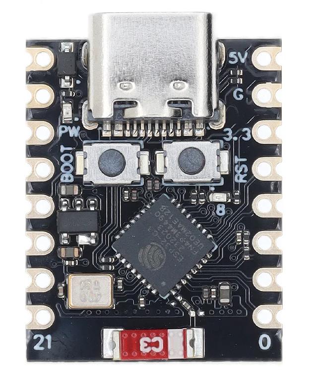
Use the module ESP32-C3 SuperMini with the Arduino IDE with the example code Blink. The “Blink” Arduino sketch is a small program that does nothing else than blink the built-in LED.
All the steps are described here, so that even a beginner can follow.
The code
I modified the program for the ESP32-C3 SuperMini:
/*
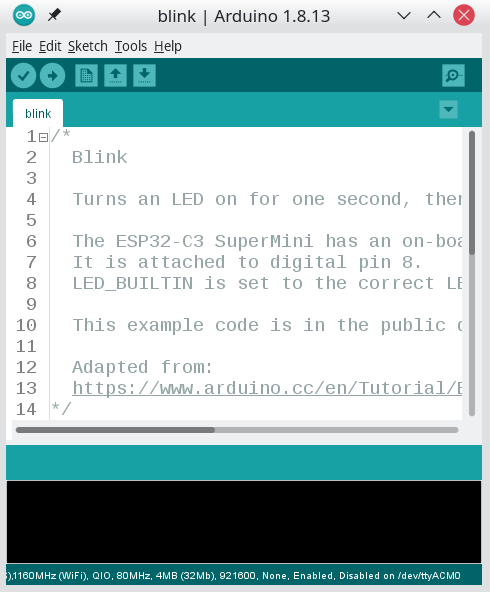
Blink
Turns an LED on for one second, then off for one second, repeatedly.
The ESP32-C3 SuperMini has an on-board LED you can control.
It is attached to digital pin 8.
LED_BUILTIN is set to the correct LED pin.
This example code is in the public domain.
Adapted from:
https://www.arduino.cc/en/Tutorial/BuiltInExamples/Blink
*/
// the LED is at pin GPIO8
#define LED_BUILTIN 8
// the setup function runs once when you press reset or power the board
void setup() {
// initialize digital pin LED_BUILTIN as an output.
pinMode(LED_BUILTIN, OUTPUT);
}
// the loop function runs over and over again forever
void loop() {
digitalWrite(LED_BUILTIN, LOW); // turn the LED on (LOW is the voltage level)
delay(100); // wait for a second
digitalWrite(LED_BUILTIN, HIGH); // turn the LED off by making the voltage HIGH
delay(900); // wait for a second
}
The Arduino IDE requires the .ino file to be in a folder with the same name as the .ino file.
Save the above code in a file with the name blink.ino in a new folder named blink.
Install the Arduino IDE
I have the version 1.8.13 installed. Probably, newer versions should work as well.
You can now double-click on the .ino file you created to load it in the Arduino IDE.
Adding ESP32 Board Support
Open the Arduino IDE.
Navigate to File > Preferences.
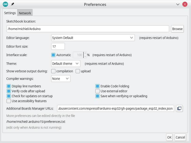
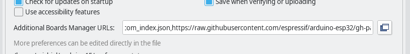
In the “Additional Board Manager URLs” field, add the following URL:
https://raw.githubusercontent.com/espressif/arduino-esp32/gh-pages/package_esp32_index.json
If there are already URLs in this field, you have to add it at the end, separated from the previous one with a comma: ,.
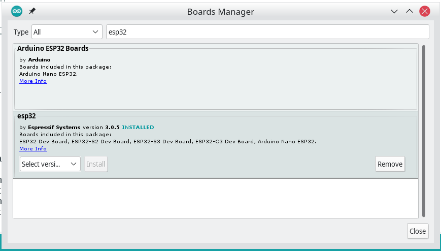
Install the ESP32 boards
To install the ESP32 boards from Espressif, go to the Boards Manager and install the boards:
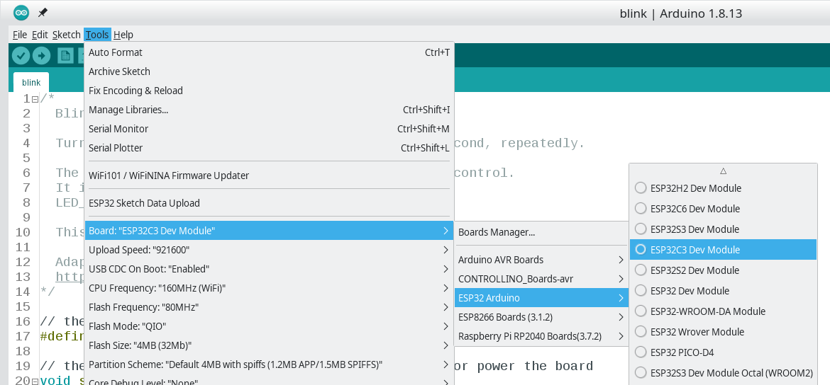
Select the correct board
We use the board “ESP32C3 Dev Module”.
Use the correct settings
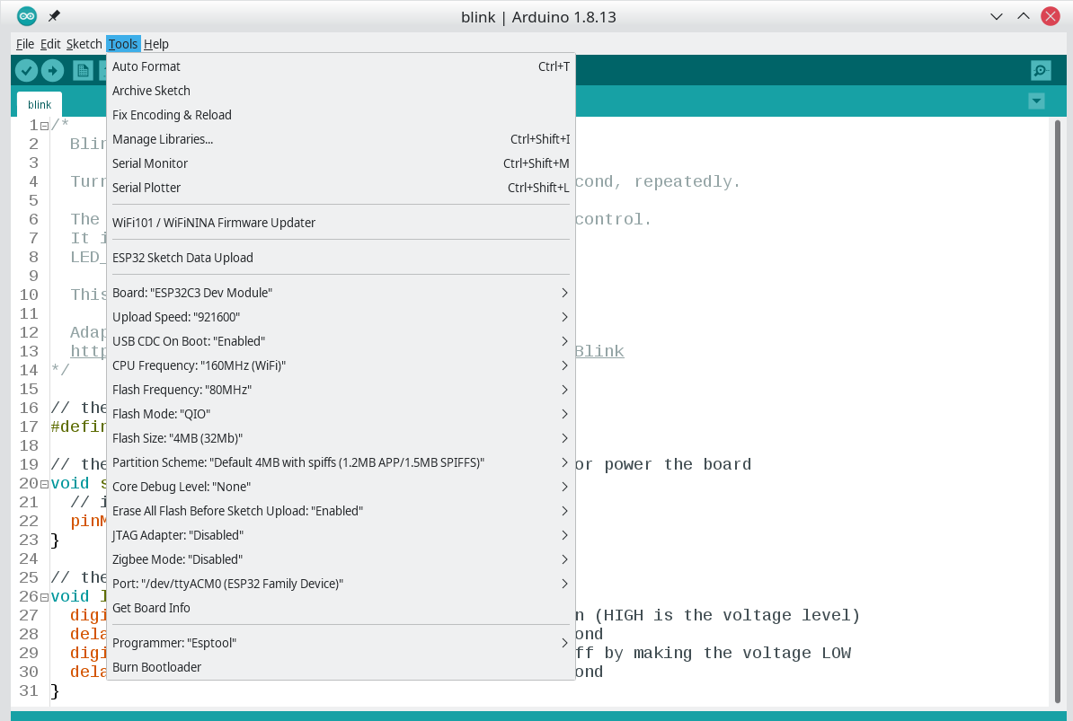
See that all these are correct.
| Setting | Value |
|---|---|
| Board | ESP32C3 Dev Module |
| Upload Speed | 921600 |
| USB CDC On Boot | Enabled |
| CPU Frequency | 160MHz (Wifi) |
| Flash Frequency | 80MHz |
| Flash Mode | QIO |
| Flash Size | 4MB (32Mb) |
| Partition Scheme | Default 4MB with spiffs (1.2MB APP/1.5MB SPIFFS) |
| Core Debug Level | None |
| Erase All Flash Before Sketch Upload | Enabled |
| JTAG Adapter | Disabled |
| Zigbee Mode | Disabled |
| Port | (depends on your PC and OS - see below) |
| Programmer | Esptool |
Port selection
Since a PC has multiple USB ports, the Arduino IDE needs to figure out which one is connected to our board.
On my PC, I see many ports - only one is the Espressif one:
michiel@Delphinus:/home> lsusb
Bus 002 Device 019: ID 0b95:1790 ASIX Electronics Corp. AX88179 Gigabit Ethernet
Bus 002 Device 018: ID 0bda:0411 Realtek Semiconductor Corp. Hub
Bus 002 Device 001: ID 1d6b:0003 Linux Foundation 3.0 root hub
Bus 001 Device 007: ID 0a5c:5842 Broadcom Corp. 58200
Bus 001 Device 005: ID 0bda:565c Realtek Semiconductor Corp. Integrated_Webcam_HD
Bus 001 Device 053: ID 303a:1001 Espressif USB JTAG/serial debug unit
Bus 001 Device 048: ID 18f8:0f99 [Maxxter] Optical gaming mouse
Bus 001 Device 008: ID 8087:0026 Intel Corp. AX201 Bluetooth
Bus 001 Device 049: ID 1a40:0101 Terminus Technology Inc. Hub
Bus 001 Device 047: ID 1a2c:645a China Resource Semico Co., Ltd USB Keyboard
Bus 001 Device 046: ID 0bda:5411 Realtek Semiconductor Corp. RTS5411 Hub
Bus 001 Device 001: ID 1d6b:0002 Linux Foundation 2.0 root hub
michiel@Delphinus:/home>
Espressif gives the following advise to determine the correct port on Windows:
Check the list of identified COM ports in the Windows Device Manager. Disconnect ESP32 and connect it back, to verify which port disappears from the list and then shows back again.
On Linux, Espressif advises to use this command:
To check the device name for the serial port of your ESP32 board (or external converter dongle), run this command two times, first with the board/dongle unplugged, then with plugged in. The port which appears the second time is the one you need:
Indeed, it works for me, but it is not very easy to spot (the /dev/ttyACM0 was added)::
michiel@Delphinus:/home> ls /dev/tty*
/dev/tty    /dev/tty20  /dev/tty33  /dev/tty46  /dev/tty59    /dev/ttyS12  /dev/ttyS25
/dev/tty0   /dev/tty21  /dev/tty34  /dev/tty47  /dev/tty6     /dev/ttyS13  /dev/ttyS26
/dev/tty1   /dev/tty22  /dev/tty35  /dev/tty48  /dev/tty60    /dev/ttyS14  /dev/ttyS27
/dev/tty10  /dev/tty23  /dev/tty36  /dev/tty49  /dev/tty61    /dev/ttyS15  /dev/ttyS28
/dev/tty11  /dev/tty24  /dev/tty37  /dev/tty5   /dev/tty62    /dev/ttyS16  /dev/ttyS29
/dev/tty12  /dev/tty25  /dev/tty38  /dev/tty50  /dev/tty63    /dev/ttyS17  /dev/ttyS3
/dev/tty13  /dev/tty26  /dev/tty39  /dev/tty51  /dev/tty7     /dev/ttyS18  /dev/ttyS30
/dev/tty14  /dev/tty27  /dev/tty4   /dev/tty52  /dev/tty8     /dev/ttyS19  /dev/ttyS31
/dev/tty15  /dev/tty28  /dev/tty40  /dev/tty53  /dev/tty9     /dev/ttyS2   /dev/ttyS4
/dev/tty16  /dev/tty29  /dev/tty41  /dev/tty54  /dev/ttyACM0  /dev/ttyS20  /dev/ttyS5
/dev/tty17  /dev/tty3   /dev/tty42  /dev/tty55  /dev/ttyS0    /dev/ttyS21  /dev/ttyS6
/dev/tty18  /dev/tty30  /dev/tty43  /dev/tty56  /dev/ttyS1    /dev/ttyS22  /dev/ttyS7
/dev/tty19  /dev/tty31  /dev/tty44  /dev/tty57  /dev/ttyS10   /dev/ttyS23  /dev/ttyS8
/dev/tty2   /dev/tty32  /dev/tty45  /dev/tty58  /dev/ttyS11   /dev/ttyS24  /dev/ttyS9
michiel@Delphinus:/home>
BTW: ACM stands for “Abstract Control Module”, which is an element of the USB standard.
Put the board in boot-mode
When the board is powered up (or reset), the processor first runs some Espressif initialisation code.
One of the things this initialisation code does, is checking if the Boot button is held down. Normally, this button is not held down, and then the initialisation code will start the user sketch.
However, if the Boot button is held down, the board enters flashing mode. In this mode, the board is waiting to communicate over the USB bus with the PC, and allows the PC to program the board’s internal flash memory.
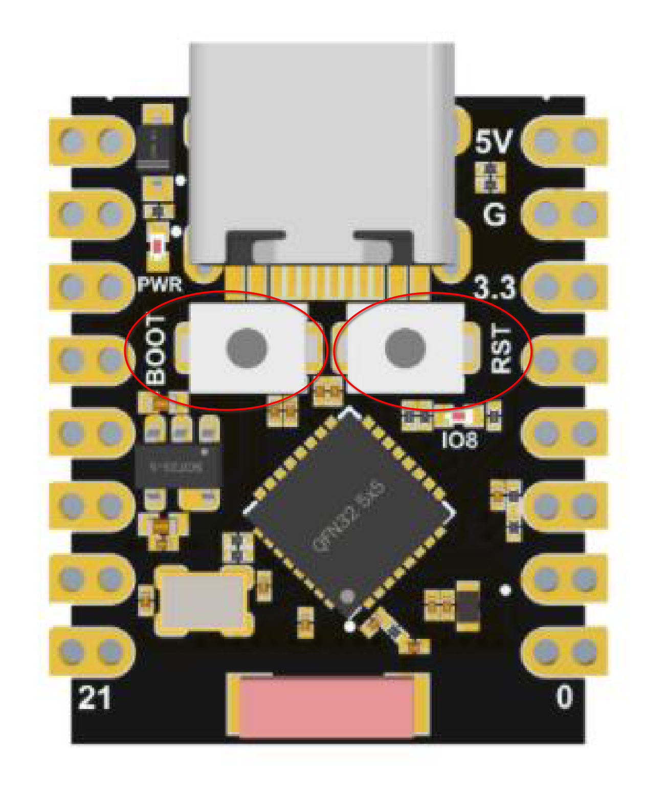
- Press the
Bootbutton and keep it down. - Press the
Resetbutton and release. - Wait a few seconds.
- Release the
Bootbutton.
Now the Red Power LED will be on, the other one not.
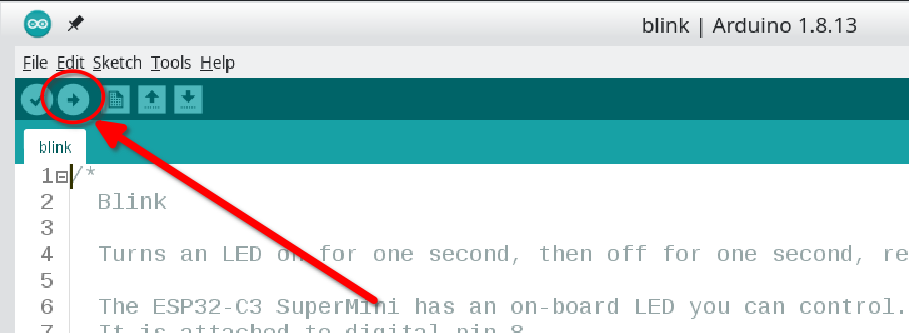
Program the board
Press the Upload button in the Arduino IDE.
The following apears in the console of the IDE:
Sketch uses 273282 bytes (20%) of program storage space. Maximum is 1310720 bytes.
Global variables use 12284 bytes (3%) of dynamic memory, leaving 315396 bytes for local variables. Maximum is 327680 bytes.
esptool.py v4.6
Serial port /dev/ttyACM0
Connecting...
Chip is ESP32-C3 (revision v0.4)
Features: WiFi, BLE
Crystal is 40MHz
MAC: 64:e8:33:84:1e:dc
Uploading stub...
Running stub...
Stub running...
Changing baud rate to 921600
Changed.
Configuring flash size...
Erasing flash (this may take a while)...
Chip erase completed successfully in 20.7s
Compressed 18688 bytes to 12099...
Writing at 0x00000000... (100 %)
Wrote 18688 bytes (12099 compressed) at 0x00000000 in 0.3 seconds (effective 491.5 kbit/s)...
Hash of data verified.
Compressed 3072 bytes to 146...
Writing at 0x00008000... (100 %)
Wrote 3072 bytes (146 compressed) at 0x00008000 in 0.0 seconds (effective 492.3 kbit/s)...
Hash of data verified.
Compressed 8192 bytes to 47...
Writing at 0x0000e000... (100 %)
Wrote 8192 bytes (47 compressed) at 0x0000e000 in 0.1 seconds (effective 657.4 kbit/s)...
Hash of data verified.
Compressed 284320 bytes to 158124...
Writing at 0x00010000... (10 %)
Writing at 0x0001bf4c... (20 %)
Writing at 0x00023bba... (30 %)
Writing at 0x0002ac1e... (40 %)
Writing at 0x000309fb... (50 %)
Writing at 0x0003704f... (60 %)
Writing at 0x0003cdb5... (70 %)
Writing at 0x00043e5a... (80 %)
Writing at 0x0004af37... (90 %)
Writing at 0x00051332... (100 %)
Wrote 284320 bytes (158124 compressed) at 0x00010000 in 2.5 seconds (effective 893.6 kbit/s)...
Hash of data verified.

Leaving...
Hard resetting via RTS pin...
Reset after programming
Since this board does not support resetting with the RTS pin, we need to do this manually.
Press the Reset button on the board.
The LED is blinking!
The Blue LED is blinking.