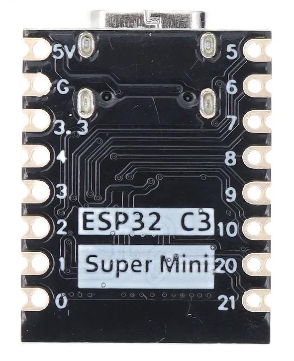
ESP32-C3 SuperMini
ESP32-C3 is a single-core Wi-Fi and Bluetooth 5 (LE) microcontroller SoC, based on the open-source RISC-V architecture. See https://espressif.github.io/esp32-c3-book-en/
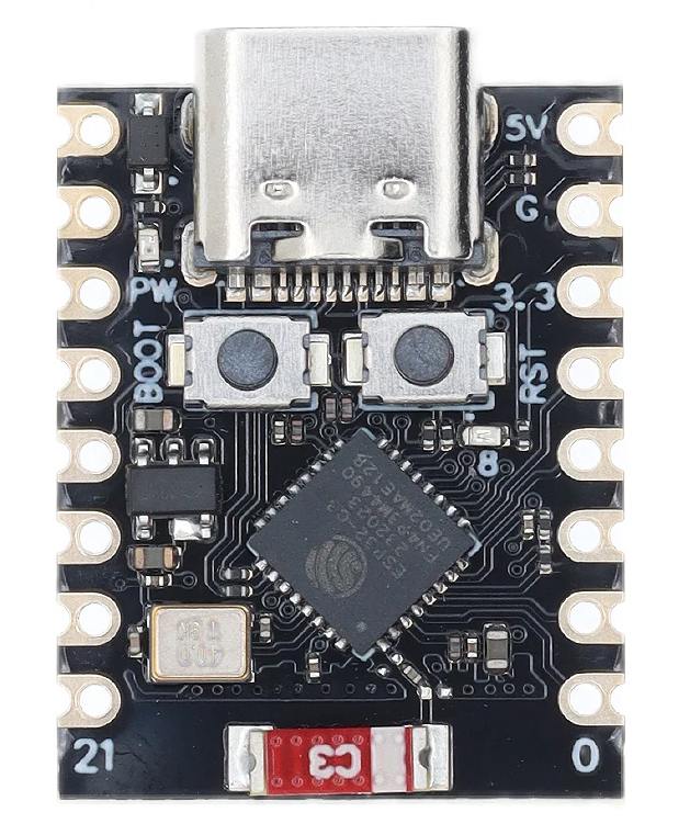
The board is fitted with a "ESP-C3-FN4", which means it has a 4MB SPI flash memory inside, and is suitable for temperature range -40°C .. 85°C.
The ESP32-FN4 is marked "Not recommended for new designs (NRND)" since august 2023. The only difference with its successor, the ESP32-C3FH4, is the temperature range, which is -40°C .. 105°C for the latter.
There exists also a version of the ESP32-C3 SuperMini with a 0.42 inch OLED display on board. The display resolution is 72 by 40 pixels and it is very small.
Supplier information
If external power supply is required, just connect the + level of the external power supply to the position of 5V, GND connects to the negative terminal. (Support 3.3 ~ 6V power supply). Remember that when connecting the external power supply, you cannot access USB, USB and external power supply can only choose one.
Enter the download mode: Hold down the BOOT button of the ESP32-C3, press the RESET button, release the RESET button, and then release the BOOT button. Then the ESP32-C3 will enter the download mode. (Each connection needs to re-enter the download mode, sometimes press once, the port instability will be disconnected, you can judge by the port identification sound)
How to use MicroPython: https://micropython.org/download/ESP32_GENERIC_C3/ and https://docs.micropython.org/en/latest/ .
Features
- ESP32C3 SuperMini is an IoT mini development board based on the Espressif ESP32-C3 WiFi/Bluetooth dual-mode chip.
- ESP32-C3 is a 32-bit RISC-V CPU, which can perform 32-bit single-precision operations and has powerful computing capabilities.
- It has excellent radio frequency performance and supports IEEE 802.11 b/g/n WiFi and Bluetooth 5 (LE) protocols.
- The board comes with an external antenna to enhance signal strength for wireless applications.
- It also has a small and exquisite appearance combined with a single-sided surface mount design.
- It is equipped with rich interfaces, with 11 digital I/Os that can be used as PWM pins and 4 analog I/Os that can be used as ADC pins.
- It supports four serial interfaces including UART, I2C and SPI.
- There is also a small reset button and a bootloader mode button on the board.
- ESP32-C3 SuperMini is positioned as a high-performance, low-power, cost-effective IoT mini development board, suitable for low-power IoT applications and wireless wearable applications.
- The ESP-C3 does NOT have a FPU (Floating Point Unit).
Datasheet ESP32-C3
Properties
- CPU: ESP32-C3, 32-bit RISC-V single-core processor
- Operating frequency: 160 MHz
- SRAM: 400KB
- ROM:374KB
- ADC: 2*12-bit SARADC, 6 channels
- WiFi: 802.11b/g/n protocol, 2.4GhHz, supports Station mode, SoftAP mode, SoftAP+Station mode, mixed mode
- Bluetooth: BT 5.0
- Power consumption: Deep sleep power consumption is about 43μA
- Rich on-chip resources: 400KB SRAM, 384KB ROM
- Rich interfaces: 1xI2C, 1xSPI, 2xUART, 11xGPIO(PWM), 4xADC
- Single-sided component, surface mount design
- Classic form factor for wearables and small projects
- Robust security features: Crypto hardware accelerator supporting AES-128/256, hashing, RSA, HMAC, digital signatures and secure boot
- Onboard LED blue light, GPIO8 pin
- Size: 22.52x18mm
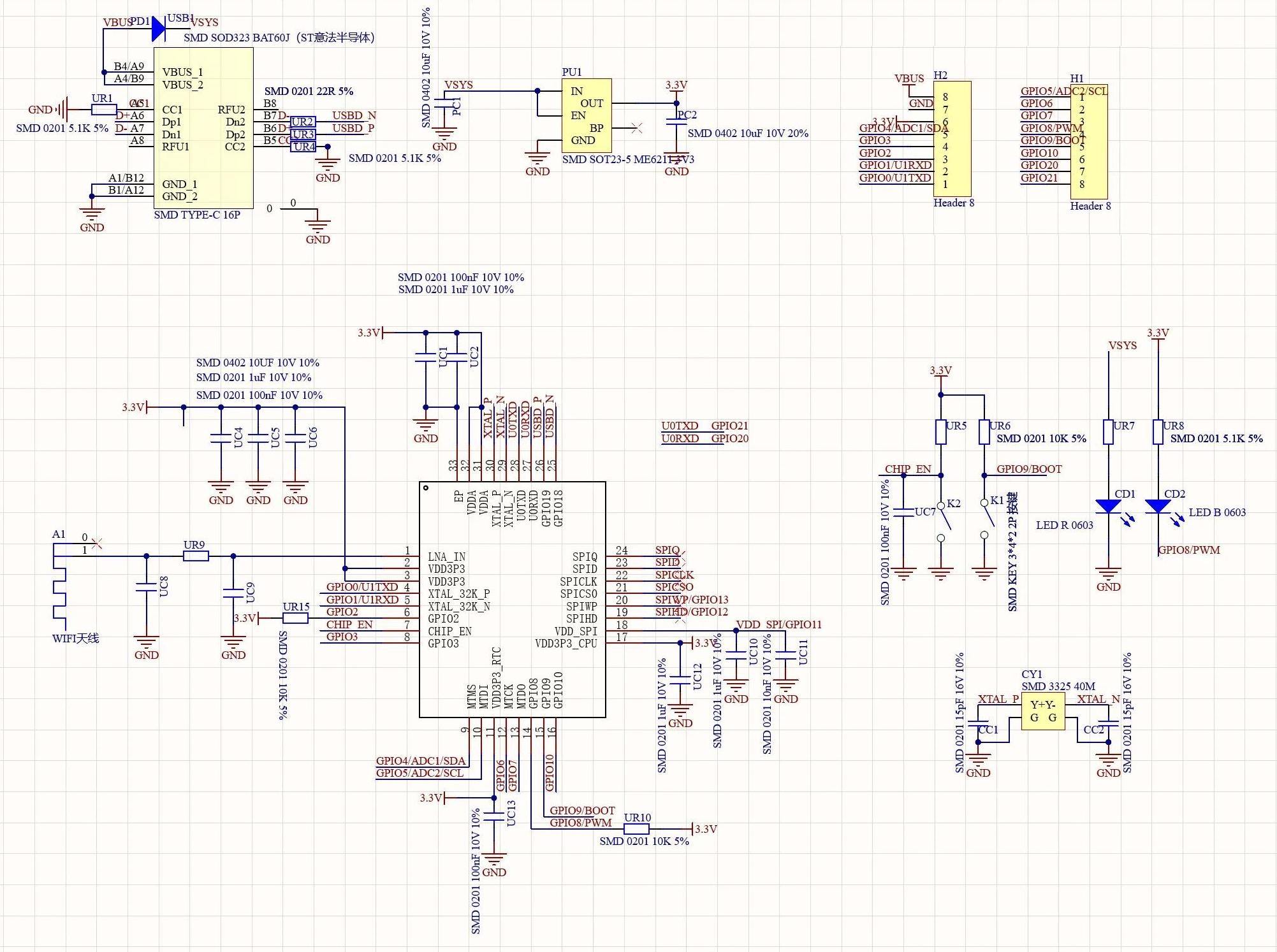
Schema and connections
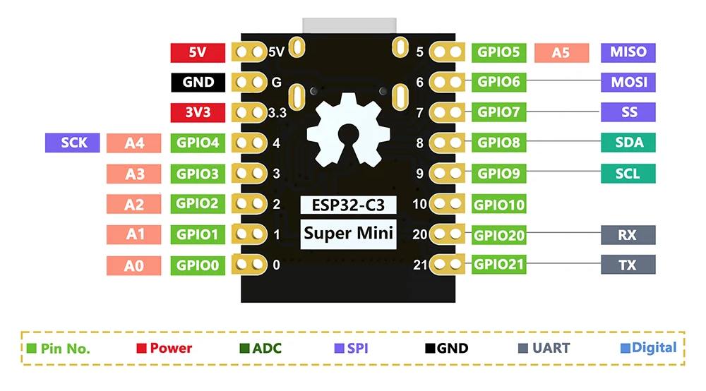
The pinnumbers used for Arduino:
static const uint8_t TX   = 21;
static const uint8_t RX   = 20;

static const uint8_t SDA  = 8;
static const uint8_t SCL  = 9;

static const uint8_t SS   = 7;
static const uint8_t MOSI = 6;
static const uint8_t MISO = 5;
static const uint8_t SCK  = 4;

static const uint8_t A0   = 0;
static const uint8_t A1   = 1;
static const uint8_t A2   = 2;
static const uint8_t A3   = 3;
static const uint8_t A4   = 4;
static const uint8_t A5   = 5;
The build-in LED is at GPIO8, so you can include this in the "blink" Arduino sketch to make it work:
// the LED is at pin  GPIO8
#define LED_BUILTIN 8
Use with Arduino IDE
The ESP32-C3 is different compared to other Arduino boards in that you must configure the Arduino IDE to communicate via the USB CDC serial port. Select Tools > USB CDC On Boot > Enabled from the Arduino IDE menus.
See the complete beginners description of using the Arduino IDE to program this board with the sketch "Blink" at https://michiel.vanderwulp.be/post-esp32c3supermini-blink-arduino-ide.html.
Use with Platformio
I tested PlatformIO with this board. The following 'platformio.ini' file just works:
[env:esp32c3_supermini]
platform = espressif32
board = esp32-c3-devkitm-1
framework = arduino
The build-in LED only works if you add the '#define' mentioned above.
To get started, follow the description here: https://michiel.vanderwulp.be/esp32-c3-supermini-blink-platformio.html
Antenna performance
The on-board antenna works, but is not very performant. It can be improved as shown here: https://peterneufeld.wordpress.com/2025/03/04/esp32-c3-supermini-antenna-modification/
Coding examples
See here for some coding examples:
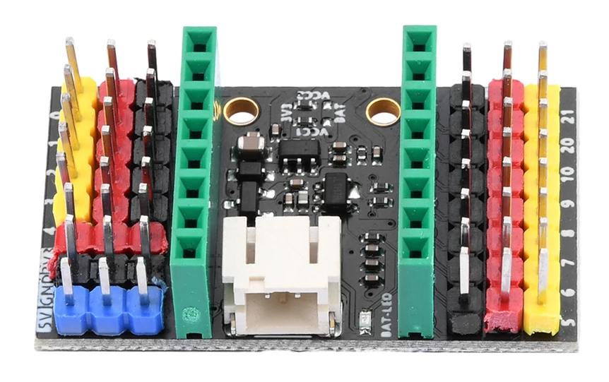
Expansion board
Supplier information
https://www.nologo.tech/product/esp32/esp32c3SuperMini/esp32C3ExpansionBoard.html
The ESP32-C3-SuperMini expansion board is specially designed for the ESP32-C3-SuperMini development board. It makes up for many shortcomings of the ESP32-C3-SuperMini development board. Using the expansion board, you can connect an external 3.7V lithium battery and support charging the lithium battery through USB. There is a green indicator while charging. When the green indicator light goes out, the lithium battery is fully charged.
This extension board makes all 10 ports accessible, which makes it convenient for users to install various sensors.
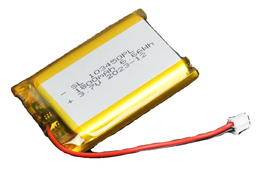
The ESP32C3supermini expansion board can be connected to a 3.7V lithium battery (PH2.0 interface lithium battery) as in following picture. The picture shows a 1800mAh battery, but I also used a somewhat larger 2500mAh one. You can find these batteries for sale by searching on the code "103450", many with the correct connector fitted.
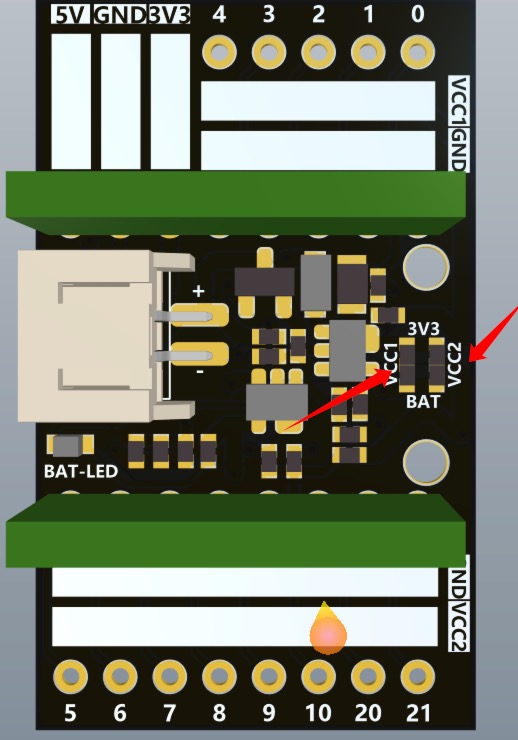
The ESP32C3supermini expansion board provides users with a better power supply solution. The expansion board has two power supplies, VCC1 and VCC2. The default voltage output by VCC1 and VCC2 is 3.3V. When you need to output a higher voltage, you can short-circuit the PCB (as shown below). At this time, the voltage output by VCC1 and VCC2 is the power supply voltage 3.7V. The default 0R resistor used at the factory is connected to 3.3V. If you need to output 3.7V, directly remove the 0R resistor and short-circuit the three pads with tin. VCC1 and VCC2 control the voltage output respectively. If you need to use one, just deal with it. Whichever one will do.
Properties
Expansion board parameters:
- Voltage: 3.7V
- External interface: PH2.0
- Size: 37.4mm*22.53mm
Chips on this board
To interprete the markings on SMD components, the following website is helpful: https://www.s-manuals.com/smd
I see the following markings on the chips on the expansion board:
S201 - Voltage regulator
- Marking (SMDcode):
- (logo) S201
- Package:
- SOT23-5
Probably this is a 3V3 voltage regulator.
Probably not a LA9010 from INNO-Tech, a charger circuit for a 4.2V battery, since the LTH7R (see below) is a battery charger circuit.
LTH7R - Battery charger
- Marking (SMDcode):
- LTH7R
- Package:
- SOT23-5
This is a LTC4054ES5-4.2 from the brand Linear Technology (owned by Analog Devices). This is a standalone linear battery charger with thermal regulation for single cell lithium-ion batteries. See the datasheet.
A19T
- Marking (SMDcode):
- A19T
- Package:
- SOT23-3
Maybe this is a Sanyo 2SK436: a general purpose N-Channel Junction Silicon FET.
Or it is a KIC77A19T from Korea Electronics, Voltage detector IC, 1.9V±1%, -Reset ODO, Rdt=240ms.
But there is a whole list of possible components at https://smd.yooneed.one/code4131.html#code413139