Origin
See https://github.com/keywish/keywish-nano-plus/tree/master/RF-Nano
The most recent documentation seems to be: https://github.com/emakefun/rf-nano
Properties
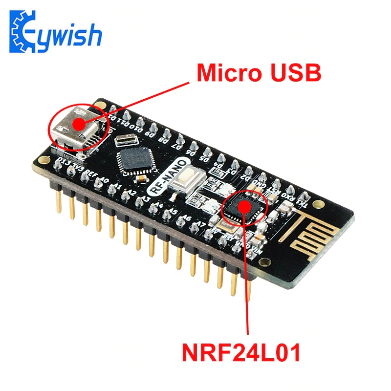
Keywish RF-Nano is an Arduino Nano V3.0 with NRF24L01+ 2.4G wireless communication chip.
The main chip is ATMEGA328P-MU QFN32, the latest bootloader (Arduino IDE 1.8.8) is burned down. It is fully compatible with the common Nano board.
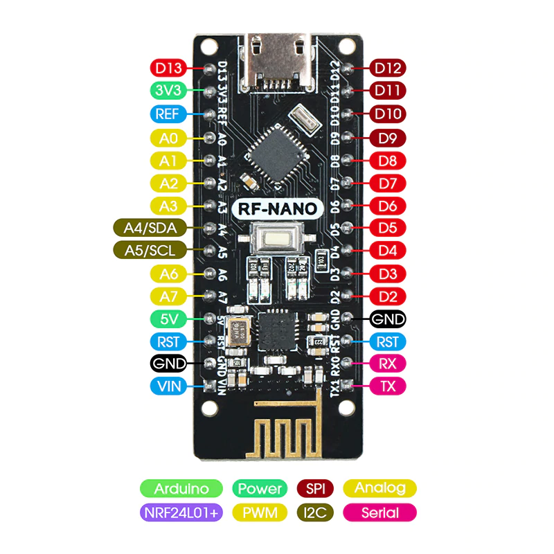
RF-Nano-Board is pin compatible with Arduino Nano V3.0 and share the same codes.
RF-Nano-Board integrates a NRF24L01+ module, which is very convenient for 2.4G wireless connect application.
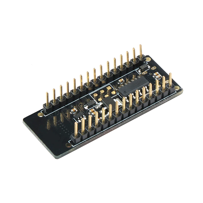
The PCB size is only 48mm x 19mm, the pin is fully compatible with Nano V3.0, no soldering needed.
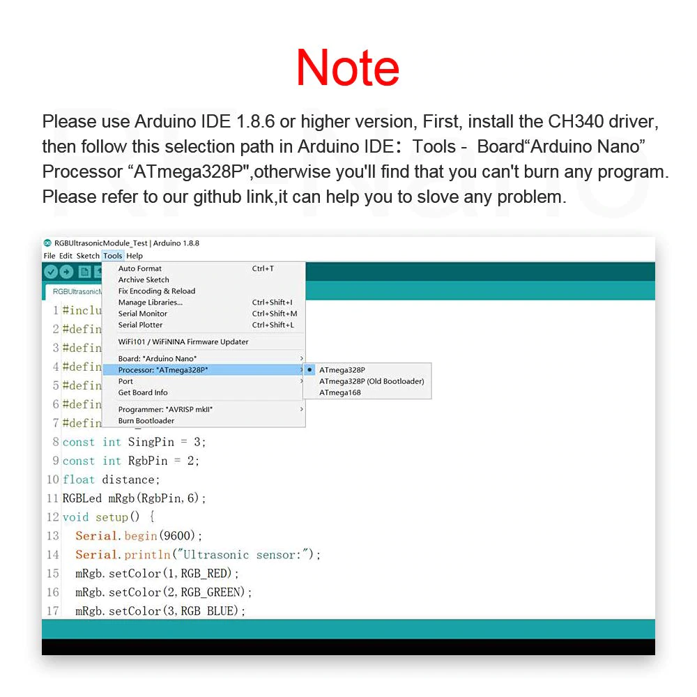
Keywish RF-Nano-Board uses CH340 chip for USB UART. You can download macOS, Windows and linux system drivers, data sheets and schematics and other informations from https://github.com/keywish/keywish-nano-plus/tree/master/RF-Nano.
- Microcontroller ATmega328P
- Nrf24L01+ 2.4G wireless
- Architecture AVR
- Operating Voltage 5 V
- Flash Memory 32 KB of which 2 KB used by bootloader
- SRAM 2 KB
- Clock Speed 16 MHz
- Analog I/O Pins 8
- EEPROM 1 KB
- DC Current per I/O Pins 40 mA (I/O Pins)
- Input Voltage 7-12 V
- Digital I/O Pins 22
- PWM Output 6
- Power Consumption 19mA
- PCB Size 48 x 18mm
- Weight 7g
The internal LED for a normal Nano is connected to pin D13.
Wiring
| Arduino Pins | Description |
|---|---|
| A0, A2, A3, A4, A5, A6, A7 (????) | Available ARDUINO analog GPIO / DIGITAL GPIO |
| D9, D10, D11,D12, D13 | Connected to nRF24L01+ 2.4 GHz Radio |
| D3, D4, D5, D6, D7, D8 (????) | Available ARDUINO digital GPIO |
See also the pdf of the schema.
Wiring for MySensors: https://forum.mysensors.org/topic/10327/rf-nano-nano-nrf24-for-just-3-50-on-aliexpress
Manual
See also the pdf of the manual.
Programming
To make this work with mysensors library:
#define MY_RF24_CE_PIN 10
#define MY_RF24_CS_PIN 9
Also:
#define MY_DEBUG_VERBOSE_RF24