Design principles
- Control the blind motors.
- React immediately on the two buttons.
- The relais shall be connected in a fail-proof way: in series. The first relais switches the motor on or off, the second relais chooses which motor runs.
- No need for interrupts and sleep mode (since we are mains powered and for simplicity). Hence we can also be repeater.
- There are two mechanical buttons combined in 3 stable positions: up, down or idle. These are mounted on the wall next to the blinds.
- No remote controlled movements while the buttons are in up or down state, only when idle.
- If a motor runs, then after a timeout, the relais shall fall off. Measurement revealed that timeout of 20s was not sufficient to move the blinds completely up - so the timeout is set to 30s.
- If a motor is running thanks to a remote command, changing one of the switch positions by hand shall stop the motor immediately for safety of operation (not yet implemented).
- If a motor has been running and then stopped, you can not start it again unless a few seconds (4) later. This to prevent damaging the relais. This happened to me with the first implementation.
- The software should protect the relais contacts from burning in or fusing by preventing to be switched on multiple times too short after each other.
Used components
- PowerSupply_HLK-PM01
- ArduinoNano5V
- RelayModule2Channel
- NRF24L01Plus
- AdapterBoardForNRF24L01
- Two buttons
- ABS box 158x90x40MM IP65
Future extensions
- Protect the relays against surges due to the inductive load with a varistor.
- Protect the relays against surges due to the inductive load by prohibiting manual operation during a short period (1s?) after switching the motor off.
- Measure current to be safe (not implemented yet)
- AC current measurement can be done in software, since no accuracy is needed (not implemented yet)
- Current sensor: CurrentMeasure5A
- If the buttons are pressed, the relais shall switch on and the motor runs. After a while, the motor current drops to zero, and the relais shall switch off (so that it does not keep drawing power). (not implemented yet)
- If the motor current does not drop to zero after a timeout, the relais shall still fall off after the timeout.
Behaviour
States
| State | Constraints | Description |
|---|---|---|
| idle | the motor is not running | |
| button up | entry: run the motor up after 30s: trigger timeout |
the motor is going up thanks to pressing a button |
| button down | entry: run the motor down after 30s: trigger timeout |
the motor is going down thanks to pressing a button |
| wait | after 4s: trigger toggleTimeout entry: stop the motors |
delay to prevent damage to the relais the motors should not be stopped and started too fast too many times - this burns out the relais contacts |
| remote up | entry: run the motor up after 30s: trigger timeout |
the motor is going up thanks to a remote command |
| remote down | entry: run the motor down after 30s: trigger timeout |
the motor is going down thanks to a remote command |
| up | entry: stop the motors | the blinds are completely up |
| down | entry: stop the motors | the blinds are completely down |
| unknown | entry: stop the motors | the motor is not running we do not know what the position of the blinds is |
Actions
| Action | Validations | Effect | Description |
|---|---|---|---|
| buttonPressedUp | not accepted when the state == up | the up button is depressed | |
| buttonPressedDown | not accepted when the state == down | the down button is depressed | |
| buttonReleasedUp | the up button is released | ||
| buttonReleasedDown | the down button is released | ||
| timeout | after a minute, we give up | ||
| remoteUp | not state up no buttons pressed |
a command has been received from remote for up | |
| remoteDown | not state down no buttons pressed |
a command has been received from remote for down | |
| interrupt | while moving automatically, someone presses a button this serves as an emergency stop |
||
| remoteStop | while moving automatically, a remote STOP command is given this serves as an emergency stop |
||
| toggleTimeout | after a few seconds, it is safe to start a next action |
Wiring
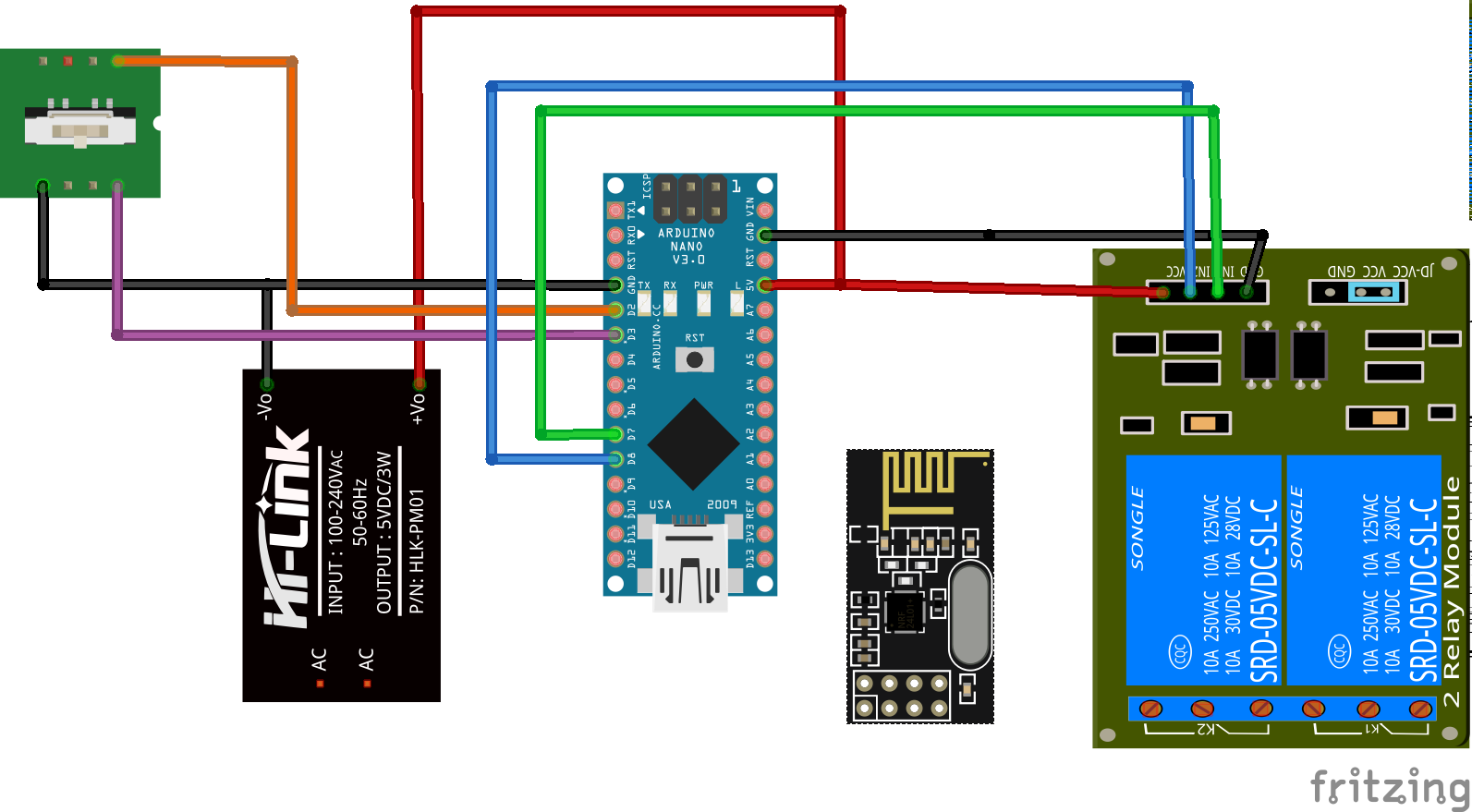
MISO = M1 MOSI = M0
| Component | Pin | Wire | Pin | Component |
|---|---|---|---|---|
| NRF24L01+ Adapter | VCC | red | 5V | PowerSupply HLK-PM01 |
| NRF24L01+ Adapter | GND | black | GND | PowerSupply HLK-PM01 |
| NRF24L01+ Adapter | CE | white | D9 | ArduinoNano5V |
| NRF24L01+ Adapter | CSN | orange | D10 | ArduinoNano5V |
| NRF24L01+ Adapter | SCK | grey | D13 | ArduinoNano5V |
| NRF24L01+ Adapter | M0 (MOSI) | yellow | D11 | ArduinoNano5V |
| NRF24L01+ Adapter | M1 (MISO) | purple | D12 | ArduinoNano5V |
| ArduinoNano5V | 5V | red | 5V | PowerSupply HLK-PM01 |
| ArduinoNano5V | GND | black | GND | PowerSupply HLK-PM01 |
| RelayModule2Channel | 5V | red | 5V | PowerSupply HLK-PM01 |
| RelayModule2Channel | GND | black | GND | PowerSupply HLK-PM01 |
| RelayModule2Channel | In1 | green | D7 | ArduinoNano5V |
| RelayModule2Channel | In2 | blue | D8 | ArduinoNano5V |
| Button 1 | orange | D2 | ArduinoNano5V | |
| Button 2 | purple | D3 | ArduinoNano5V |
Safety
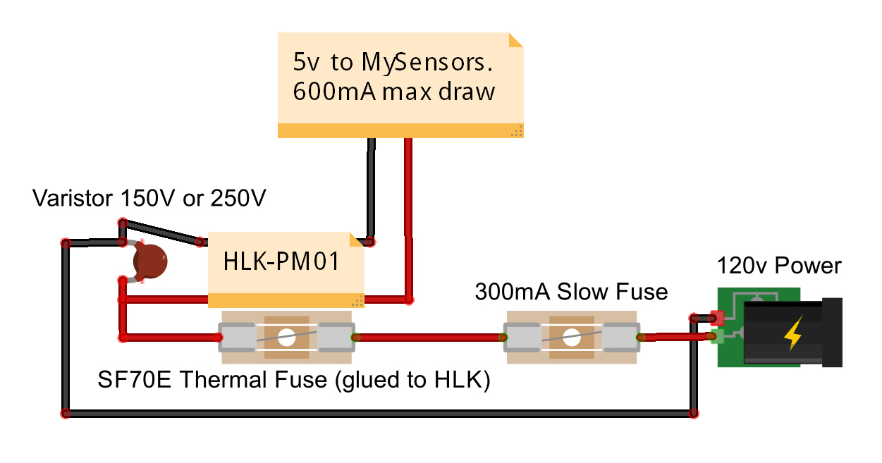
Protection with inductive load
It is advised to use a Varistor over the contacts of the relay.
See https://www.ia.omron.com/support/faq/answer/36/faq02804/
Programming
- Board: Arduino Nano
- Processor: ATmega328P (Old Bootloader)
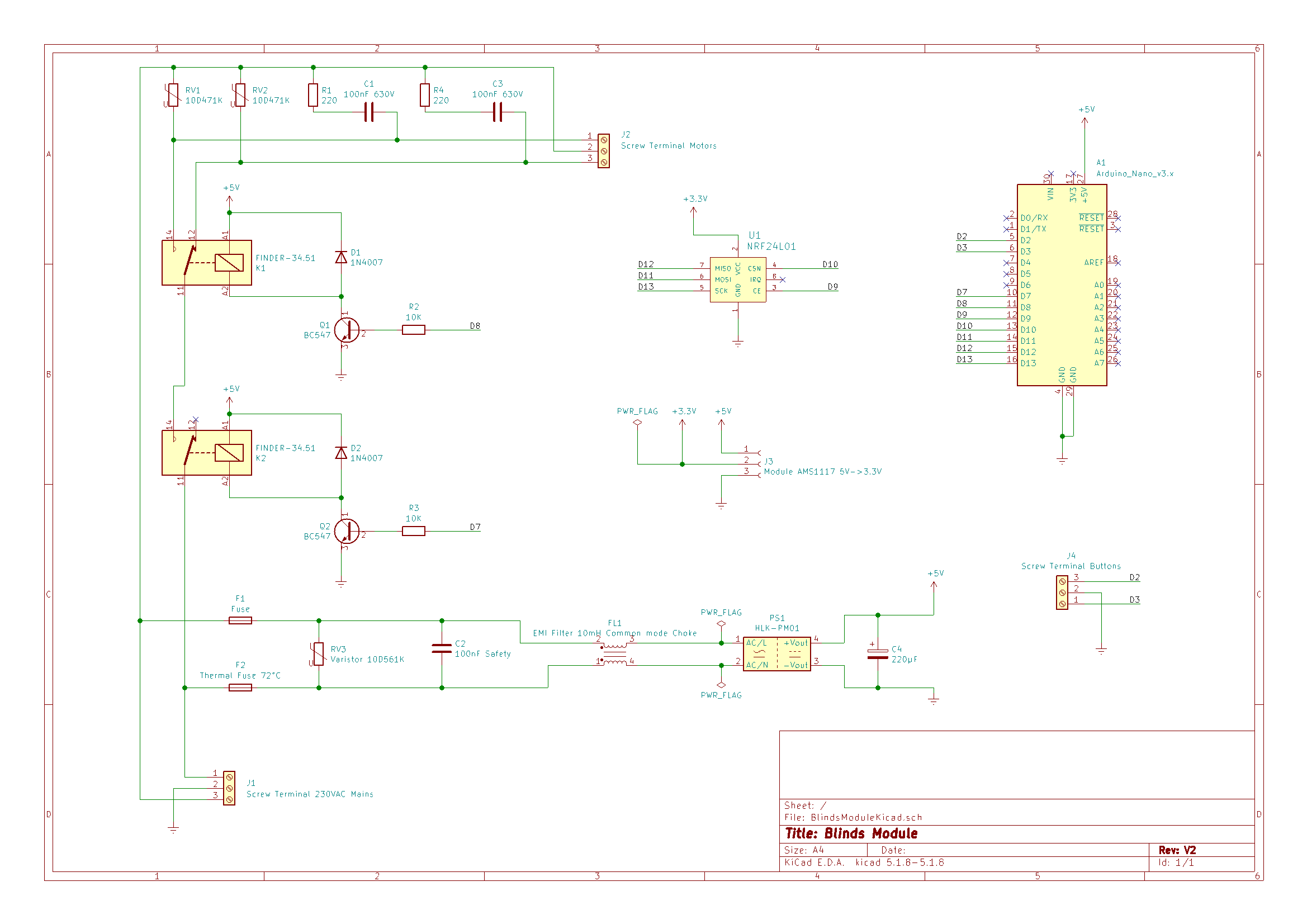
Rework: Blinds Module V2
After a few years, I reworked this module according the following complete schematics, and made a custom PCB for it:
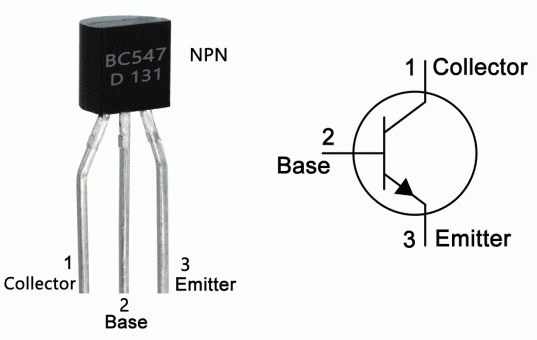
Connection of the BC547
Using Platformio
Also: using Platformio for building:
pio run -t upload -t monitor
The file platformio.ini contains:
[platformio]
src_dir = blindsmodule

[env:uno]
platform = atmelavr
;board = nanoatmega328new  <-- the board I use has an old bootloader, so this does not work!
board = nanoatmega328
framework = arduino
monitor_speed = 115200
lib_deps =
    548  ; MySensors
    thomasfredericks/Bounce2
PCB design
Designed with KiCAD.
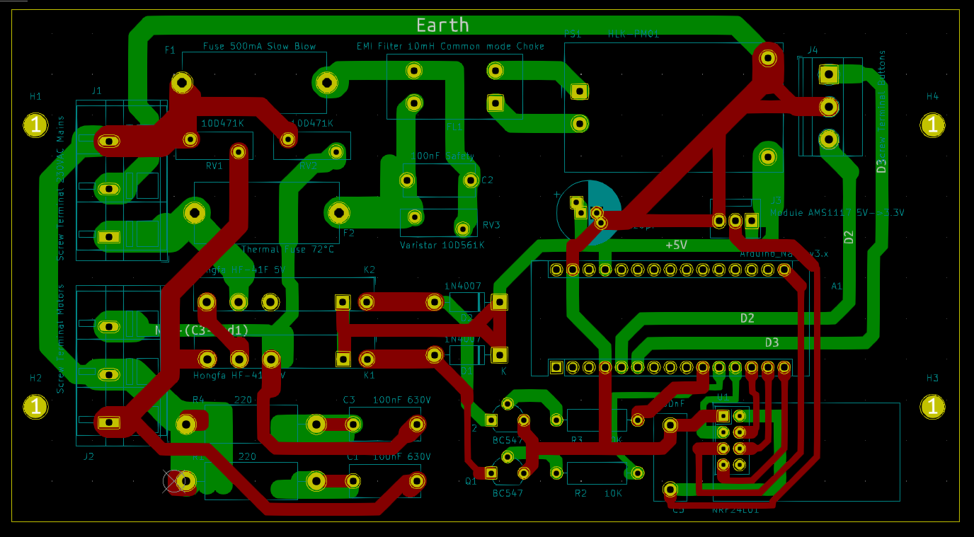
Screenshot of the PCB in KiCAD
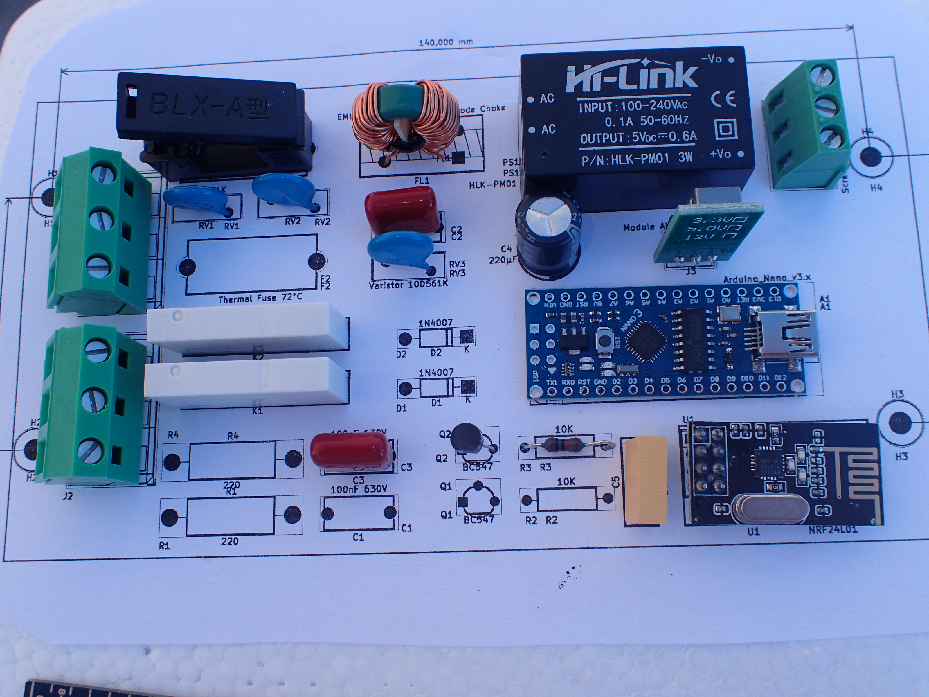
Testing the physical layout with a printout of the silkscreen and a piece of styrofoam EPS (expanded polystyrene foam)
How to solder a thermal fuse
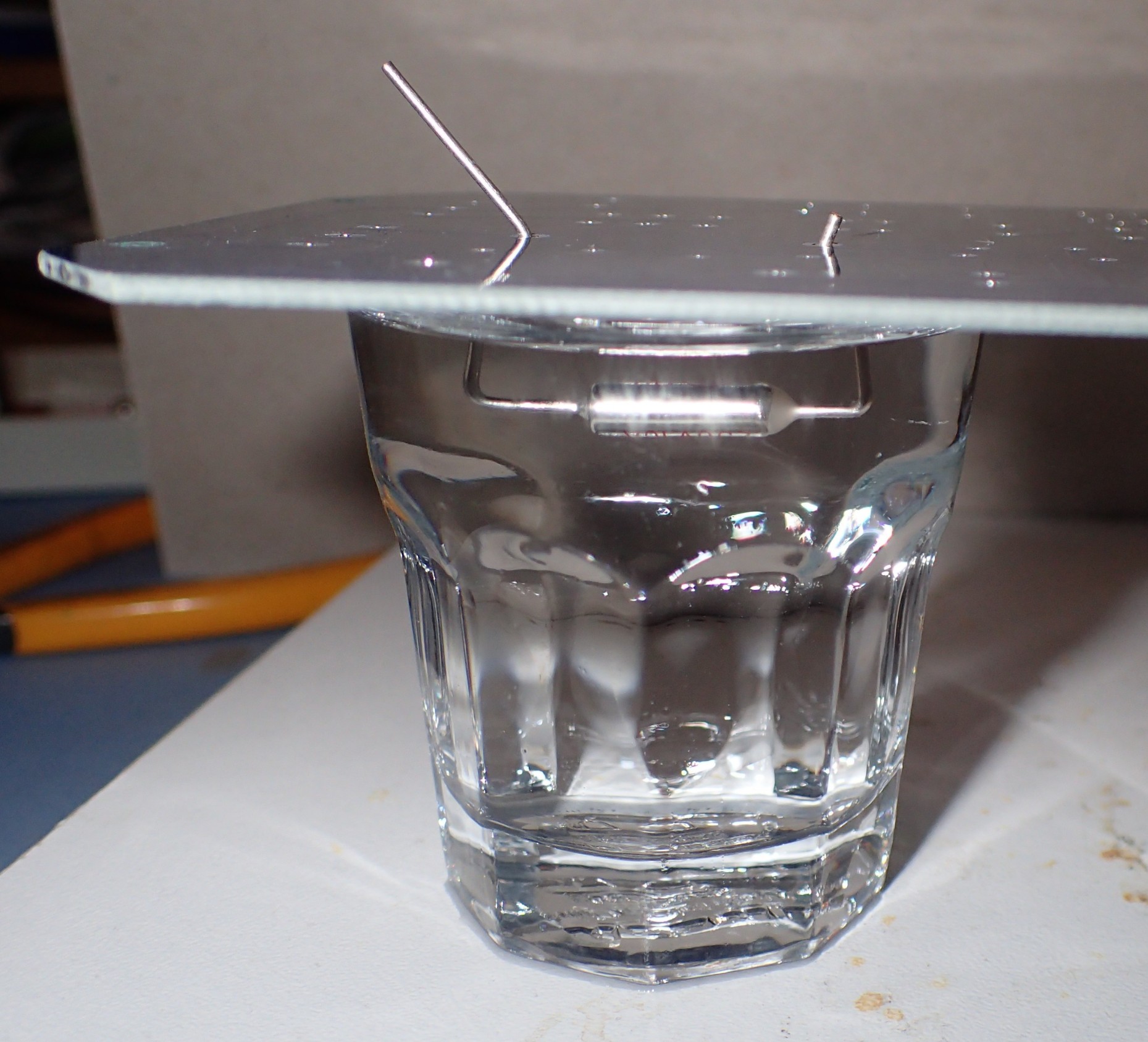
Keep the thermal fuse submerged in a glass of water!
The assembled board
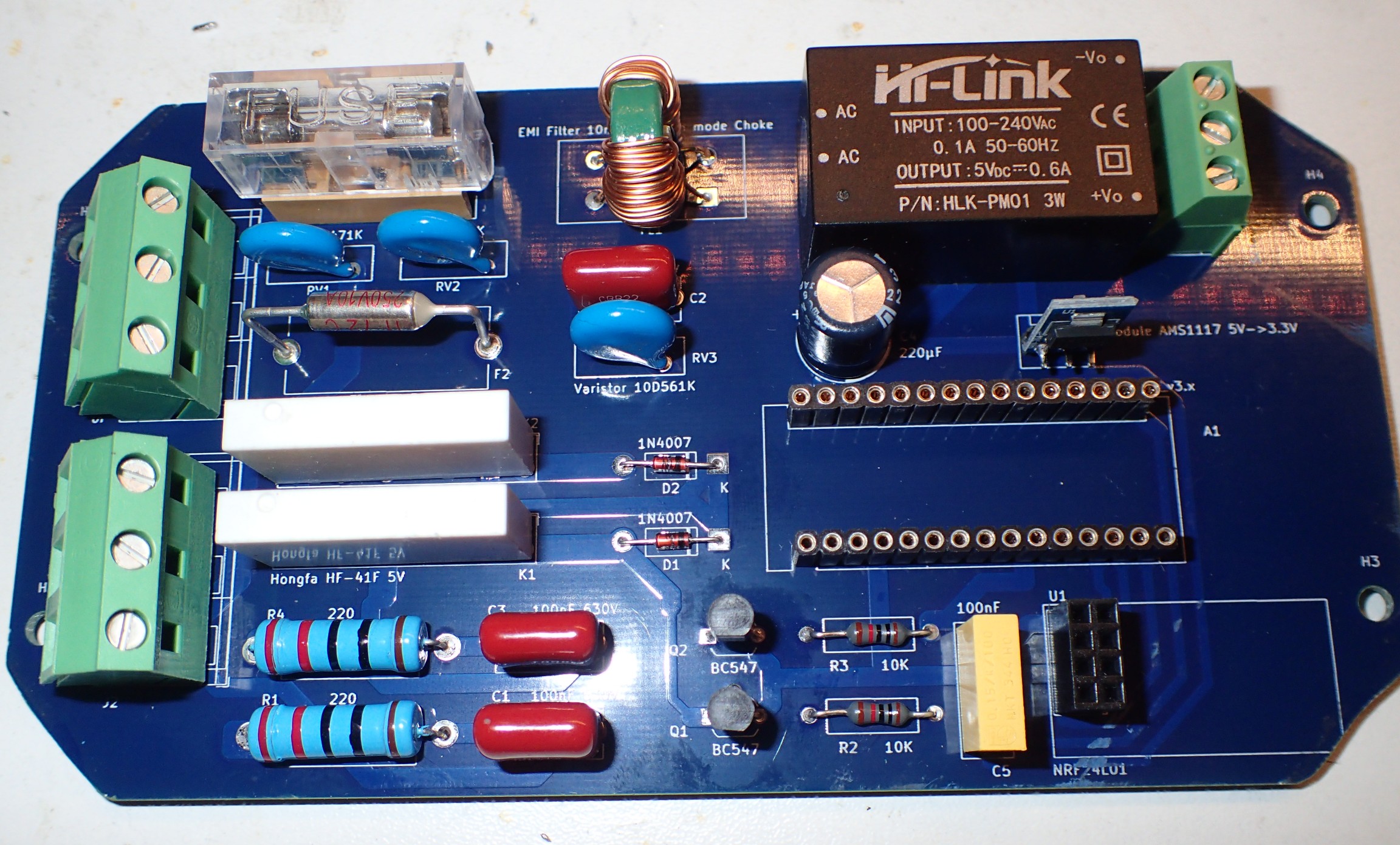
The Arduino and the radio still need to be plugged in
Software
First sign of life on the Domoticz log:
2022-04-29 11:35:02.470 MySensors-Gateway-LAN-W5100: Blinds (Blinds Module 2)
2022-04-29 11:35:02.449 Status: MySensors-Gateway-LAN-W5100: Node: 14, Sketch Name: Blinds 2
2022-04-29 11:35:02.457 Status: MySensors-Gateway-LAN-W5100: Node: 14, Sketch Version: 2.0
And on the terminal (ID 14 was already administered):
__  __       ____
|  \/  |_   _/ ___|  ___ _ __  ___  ___  _ __ ___
| |\/| | | | \___ \ / _ \ `_ \/ __|/ _ \| `__/ __|
| |  | | |_| |___| |  __/ | | \__ \  _  | |  \__ \
|_|  |_|\__, |____/ \___|_| |_|___/\___/|_|  |___/
        |___/                      2.3.2

16 MCO:BGN:INIT REPEATER,CP=RNNRA---,FQ=16,REL=255,VER=2.3.2
27 MCO:BGN:BFR
28 TSM:INIT
29 TSF:WUR:MS=0
36 TSM:INIT:TSP OK
38 TSF:SID:OK,ID=14
39 TSM:FPAR
44 ?TSF:MSG:SEND,14-14-255-255,s=255,c=3,t=7,pt=0,l=0,sg=0,ft=0,st=OK:
293 TSF:MSG:READ,0-0-14,s=255,c=3,t=8,pt=1,l=1,sg=0:0
297 TSF:MSG:FPAR OK,ID=0,D=1
335 TSF:MSG:READ,7-7-14,s=255,c=3,t=8,pt=1,l=1,sg=0:1
462 TSF:MSG:READ,17-17-14,s=255,c=3,t=8,pt=1,l=1,sg=0:1
892 TSF:MSG:READ,20-20-14,s=255,c=3,t=8,pt=1,l=1,sg=0:1
2052 TSM:FPAR:OK
2053 TSM:ID
2054 TSM:ID:OK
2056 TSM:UPL
2061 TSF:MSG:SEND,14-14-0-0,s=255,c=3,t=24,pt=1,l=1,sg=0,ft=0,st=OK:1
2069 TSF:MSG:READ,0-0-14,s=255,c=3,t=25,pt=1,l=1,sg=0:1
2074 TSF:MSG:PONG RECV,HP=1
2076 TSM:UPL:OK
2078 TSM:READY:ID=14,PAR=0,DIS=1
2085 TSF:MSG:SEND,14-14-0-0,s=255,c=3,t=15,pt=6,l=2,sg=0,ft=0,st=OK:0100
2093 TSF:MSG:READ,0-0-14,s=255,c=3,t=15,pt=6,l=2,sg=0:0100
2100 TSF:MSG:SEND,14-14-0-0,s=255,c=0,t=18,pt=0,l=5,sg=0,ft=0,st=OK:2.3.2
2110 TSF:MSG:SEND,14-14-0-0,s=255,c=3,t=6,pt=1,l=1,sg=0,ft=0,st=OK:0
2124 TSF:MSG:READ,0-0-14,s=255,c=3,t=6,pt=0,l=1,sg=0:M
2131 TSF:MSG:SEND,14-14-0-0,s=255,c=3,t=11,pt=0,l=8,sg=0,ft=0,st=OK:Blinds 2
2143 TSF:MSG:SEND,14-14-0-0,s=255,c=3,t=12,pt=0,l=3,sg=0,ft=0,st=OK:2.0
2154 TSF:MSG:SEND,14-14-0-0,s=1,c=0,t=5,pt=0,l=15,sg=0,ft=0,st=OK:Blinds Module 2
2162 MCO:REG:REQ
2167 TSF:MSG:SEND,14-14-0-0,s=255,c=3,t=26,pt=1,l=1,sg=0,ft=0,st=OK:2
2174 TSF:MSG:READ,0-0-14,s=255,c=3,t=27,pt=1,l=1,sg=0:1
2180 MCO:PIM:NODE REG=1
2182 MCO:BGN:STP
Blinds 2 2.0 - Online!
Initial state is: unknown (0).