The gateway between the NRF24L01+ network and the intranet
Design principles
- Based on
- code based on
- The gateway always has node id 0.
- The IP address is assigned dynamically by the router by DHCP, but since I instructed the router to give the same IP address every time (based on the MAC address), it works like a fixed IP address. This is called "fixed lease".
- The port used is 5003.
- The MAC address is 0xDEADBEEFFEED.
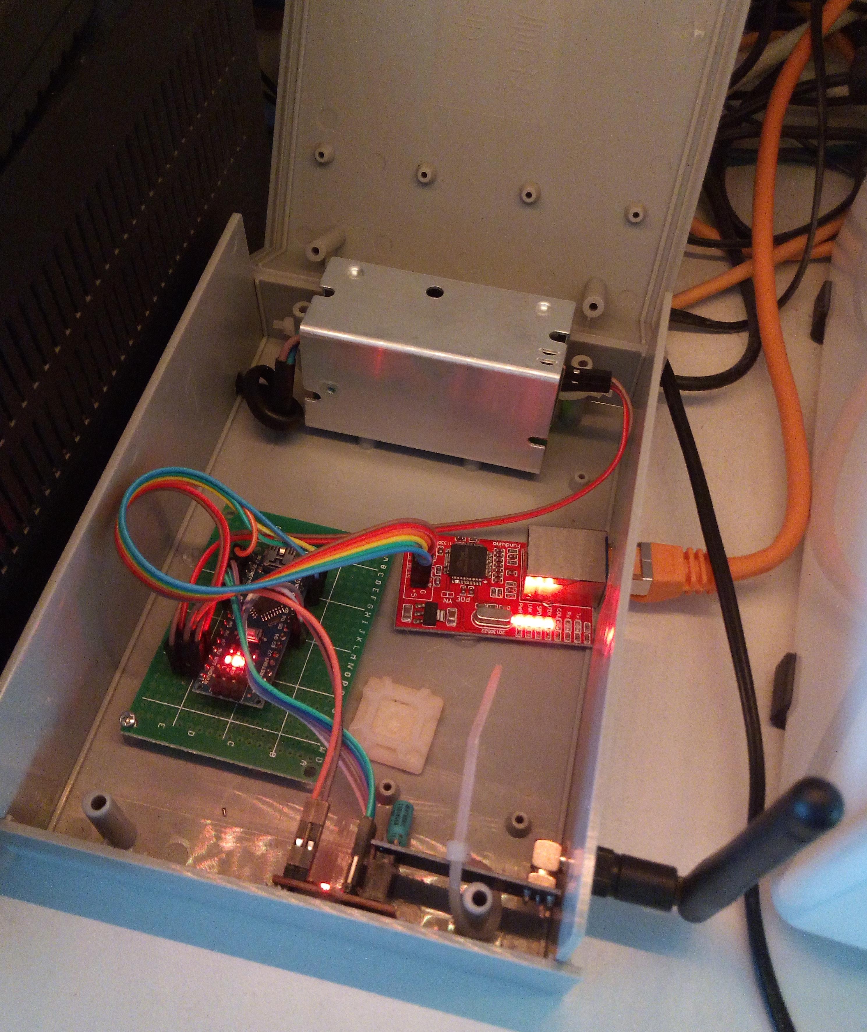
Used components
Wiring
MISO = M1 MOSI = M0
| Component | Pin | Wire | Pin | Component |
|---|---|---|---|---|
| NRF24L01+ Adapter | VCC | red | 5V | PowerSupply HLK-PM01 |
| NRF24L01+ Adapter | GND | brown | GND | PowerSupply HLK-PM01 |
| NRF24L01+ Adapter | CE | white | D5 | ArduinoNano5V |
| NRF24L01+ Adapter | CSN | grey | D6 | ArduinoNano5V |
| NRF24L01+ Adapter | SCK | purple | A0 (= 14 in the code) | ArduinoNano5V |
| NRF24L01+ Adapter | M0 (MOSI) | blue | A1 (= 15 in the code) | ArduinoNano5V |
| NRF24L01+ Adapter | M1 (MISO) | green | A2 (= 16 in the code) | ArduinoNano5V |
| ArduinoNano5V | 5V | red | 5V | PowerSupply HLK-PM01 |
| ArduinoNano5V | GND | black | GND | PowerSupply HLK-PM01 |
| W5100 Ethernet | +5 | red | 5V | PowerSupply HLK-PM01 |
| W5100 Ethernet | G | brown | GND | PowerSupply HLK-PM01 |
| W5100 Ethernet | CK (SCK) | orange | D13 | ArduinoNano5V |
| W5100 Ethernet | M1 (MISO/SO) | green | D12 | ArduinoNano5V |
| W5100 Ethernet | M0 (MOSI/SI) | yellow | D11 | ArduinoNano5V |
| W5100 Ethernet | SS (SS/CS) | blue | D10 | ArduinoNano5V |
Code
- baud rate 115200
- board: Arduino Nano
- GatewayEthernetW5100.ino
API documentation and Debug
See the following links:
| Description | Link |
|---|---|
| Serial API | https://www.mysensors.org/download/serial_api_20 |
| Debug explanation | https://www.mysensors.org/build/debug |
| Debug detailed encoding | https://www.mysensors.org/apidocs-beta/group__MyTransportgrp.html |
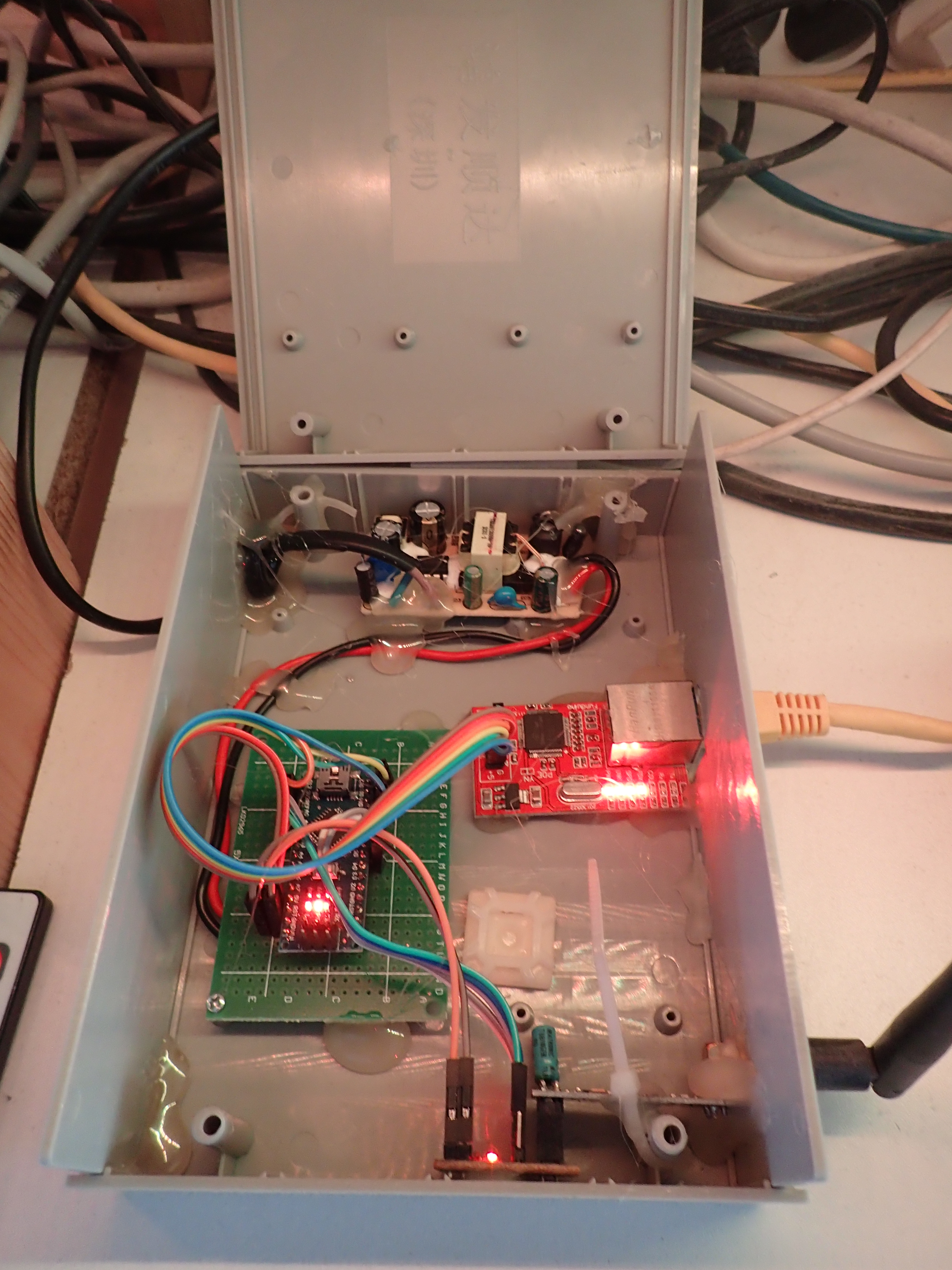
After many years
The original power supply did not live so long, I had to replace it.
There was no problem with the other components. Only the hot glue that I used to fixate the boards in the box, came loose and I had to replace.
Using a serial gateway is much more difficult than building this wired ethernet gateway, since it allowed me to replace the computer that accesses it easily. I have Domoticz reading from this gateway, and I also experimented for a while, with having a server with Node-Red reading from this gateway too - so it is possible to have two consumers of the MySensors gateway - although I do not advise this as a permanent setup.
Comments: