Supplier info
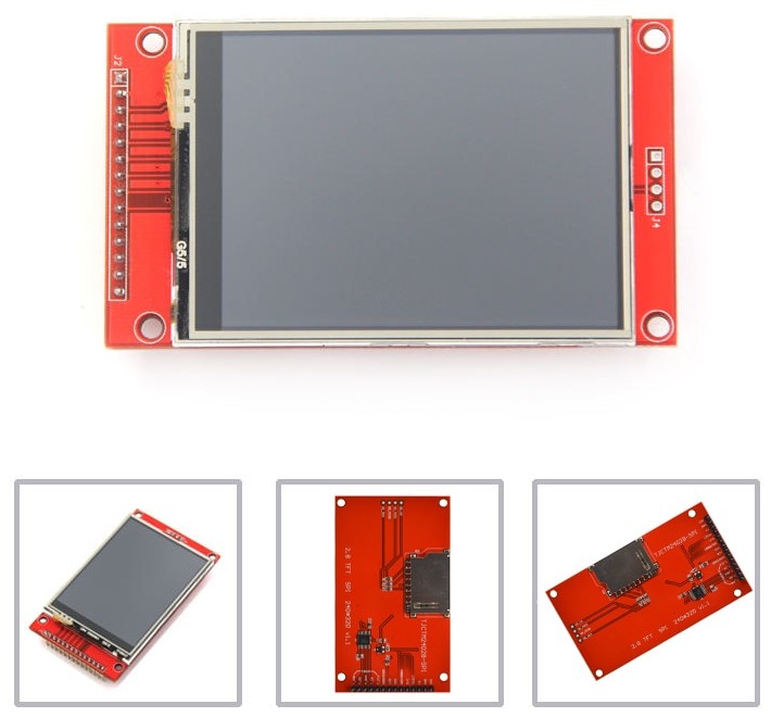
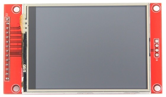
Factory Orginal 2.8” 240*320 ILI9341 Smart Display Screen 2.8inch SPI LCD TFT Module With/Without Touch TFT display.
SKU: MSP2807
A sample program is provided for 51 MCU, stm32 MCU and Arduino. Download the information here: 2.8inch_SPI_Module_ILI9341.zip.
Description
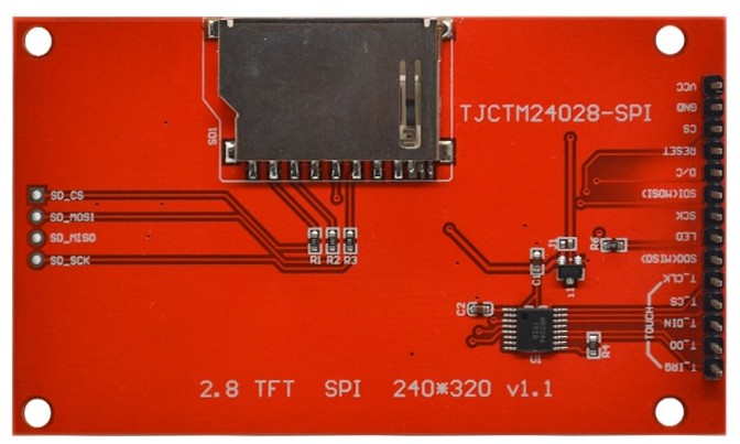
The LCD module hardware circuit includes the following parts: an LCD display control circuit, a touch screen control circuit, a backlight control circuit, and a SD card reader.
| Subject | Value |
|---|---|
| Size | 2.8 inch |
| Resolution | 240x320 |
| LCD driver IC | ILI9341V |
| Touch panel driver IC | XPT2046 |
| Power regulator (5V -> 3.3V) | XC6206 |
| Interface | 4L SPI serail port |
| PCB size | length: 86.00 mm x width 50.00 mm |
| Active area | length 57.6 mm x width 43.2 mm |
| LCD working voltage | IOVCC = VCC = 2.8V .. 3.3V |
| Backlight current | 80mA |
| Working temperature | -20°C .. +80°C |
| Touch | with or without |
| Weight | 48g |
| Number | Pin Label | Description |
|---|---|---|
| 1 | VCC | 5V/3.3V power input |
| 2 | GND | Ground |
| 3 | CS | LCD chip select signal, low level active |
| 4 | RESET | LCD reset signal, low level reset |
| 5 | DC/RS | LCD register / data selection signal, low level: register, high level: data |
| 6 | SDI(MOSI) | SPI bus write data signal |
| 7 | SCK | SPI bus clock signal |
| 8 | LED | Backlight control, lights up at high level, always on when connected to 3.3V |
| 9 | SDO(MISO) | SPI bus read data signal, if you do not need the read function, you can leave it unconnected |
The following is the touch screen signal line wiring, if you do not need to touch function or the module itself does not have touch function, you can leave them unconnected:
| Number | Pin Label | Description |
|---|---|---|
| 10 | T_CLK | Touch SPI bus clock signal |
| 11 | T_CS | Touch screen chip select signal, low level enable |
| 12 | T_DIN | Touch SPI bus input |
| 13 | T_DO | Touch SPI bus output |
| 14 | T_IRQ | Touch screen interrupt signal, low level when touch is detected |

The following is the SD card reader wiring:
| Number | Pin Label | Description |
|---|---|---|
| 15 | SD_CS | SD card reader: chip select signal, low level enable |
| 16 | SD_MOSI | SD card reader: SPI bus input |
| 17 | SD_MISO | SD card reader: SPI bus output |
| 18 | SD_SCK | SD card reader: SPI bus clock signal |
Schema
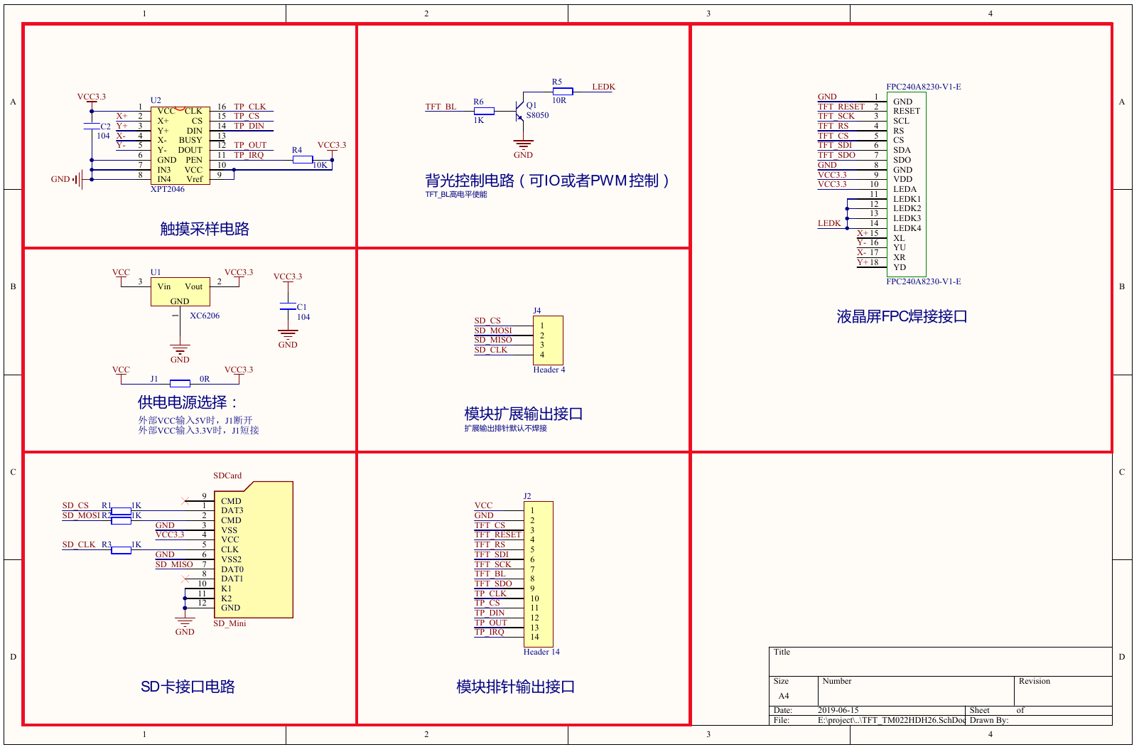
Power supply
The module can be used with 5V or 3.3V supply:
- for 5 Volt supply, the J1 should be open, and the XC6206 should be in place on the board. This is the configuration when the module leaves the factory.
- for 3.3V supply, the J1 should be closed, and the power regulator circuit XC6202 can be removed.
User comment (translated): It is possible to feed this module 5V as power supply, however it is not compatible with 5 Volt logic.
| The signals controlling the module should always be 3.3V levels, independent of the power supply choice! |
Programming with Arduino
| Library | Link | Description |
|---|---|---|
| Adafruit | https://github.com/adafruit/Adafruit_ILI9341 | library for the Adafruit ILI9341 display products |
| Bodmer TFT_ILI9341 | https://github.com/Bodmer/TFT_ILI9341 | Proportional fonts, based on the Adafruit GFX library |
| ucglib from olikraus | https://github.com/olikraus/ucglib | Color graphics library for ST7735, ILI9341, PCF8833, SSD1351, LD50T6160, ILI9163 |