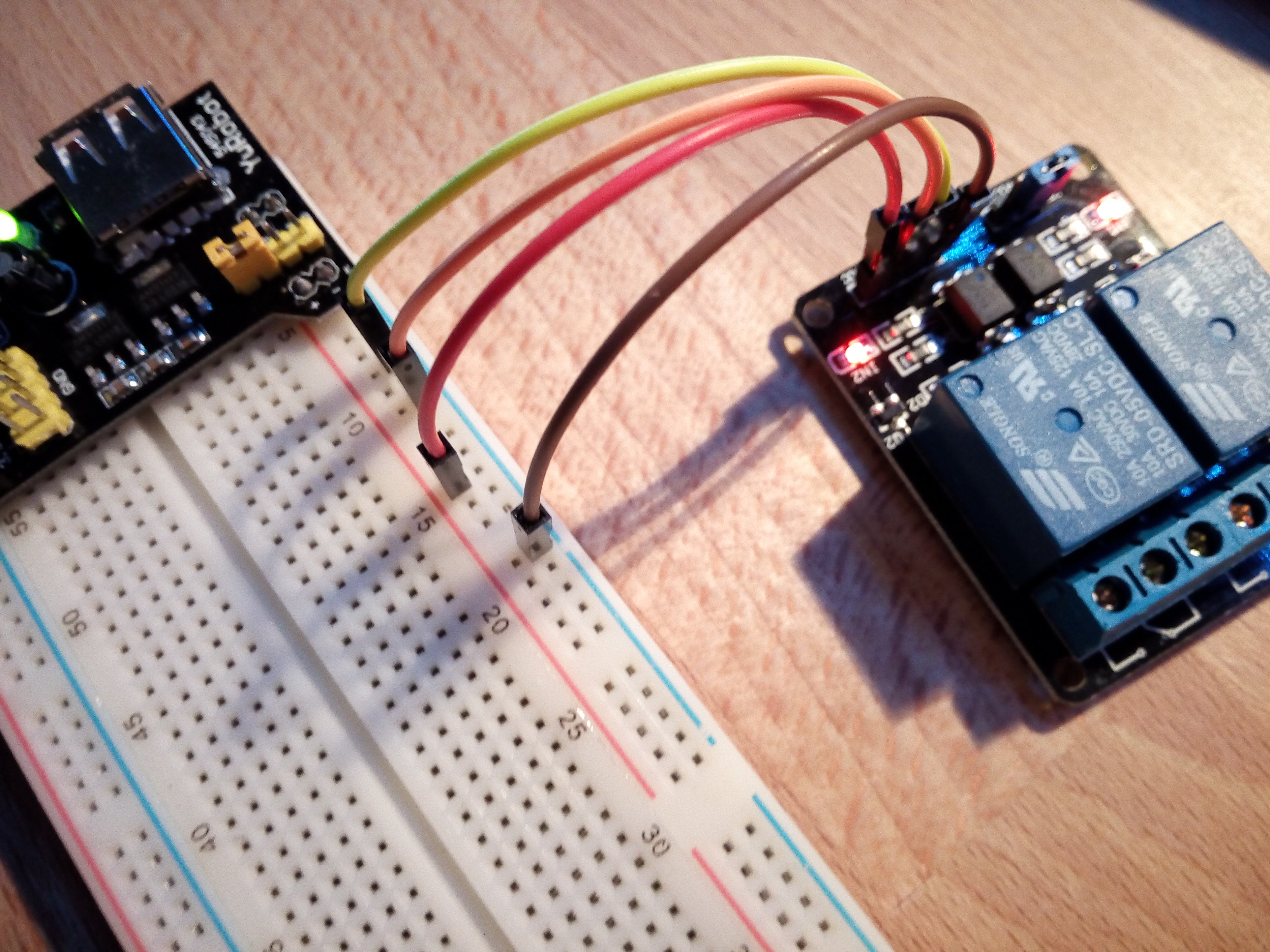
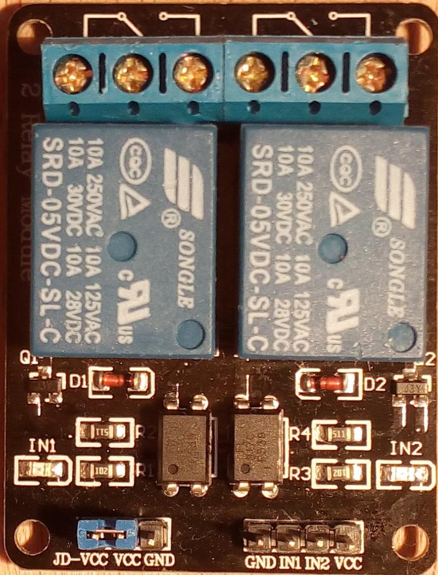
Properties
- 5V power supply
- 2 Relay SPDT (Single Pole, Double Throw)
- make input 0V to activate relais = active low input
- sink current per input pin: 1.8mA
- power supply with one relais on: 73mA
- power supply with two relais on: 140mA
- power supply with no relais on: 0mA
- FL817C - 4 Pin Dip - Optocoupler
- a red LED indicates relay on (= input low)
This module has active-low inputs!
Configuring a microcontroller to work with an active-low relay involves inverting the output logic so that a low signal turns the relay ON and a high signal turns it OFF.
E.g. with Tasmota software, you can configure the GPIO as "Relay_i" instead of simply "Relay".
Usage with CPU on 3.3V and 5V relays
The relay voltage is 5V, and the module will not work correctly with 3.3V connected to VCC.
However, feeding the module with 5V at its VCC pin, allows the use of a microcontroller running on 3.3V.
Since the inputs are active-low, there is no problem if the microcontroller pulls the relay module input low. When the microcontroller makes its output high, it carries almost 3.3V. That is too high for the relay module to switch on its relay.
My measurements reveal that when lowering the input voltage gradually, the relay will contract (click!) below 1.6V and fall back off (clack!) when increasing the voltage above 2.2V.
An other point of concern with some modules, is the situation where the microcontroller makes its output pin high (3.3V). The 5V voltage could pass the opto-coupler LED and reach the microcontroller - that is not allowed - the microcontroller can not withstand 5V ever anywhere. This does not seem a problem with this module, since I measure only 2.9V on the input pin when disconnected. I do not know how this works, since I do not have the schematics of this module.
What is the JD-VCC pin for?
The JD-VCC pin (Jumper Determined Voltage Controlled Circuit) on a double relay module is a specialized power pin used to drive the relay coils, in this case operating at 5V. It allows for separating the relay coil power from the microcontroller's low-power logic circuitry (like Arduino or Raspberry Pi), enabling opto-isolation and reducing the risk of high-current spikes damaging the controller.
Default Operation (Jumper On): The JD-VCC pin is jumpered to VCC, powering the relays directly from the Arduino/controller's 5V supply.
Isolated Operation (Jumper Off): The jumper is removed. JD-VCC is connected to an external 5V power supply to power the coils, while VCC is connected to the microcontroller 3.3V/5V for control logic. In this case you should probably also not connect both GND pins.