Supplier info
We provide module instruction manual and debugging software, please go to the following URL site for download.
http://www.shwellpro.com/download.asp
1. Product description
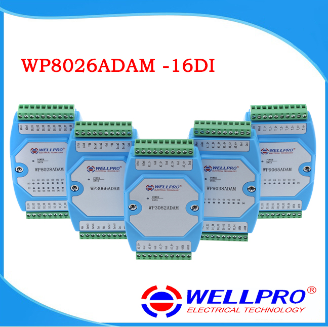
- 16ch optoelectronic isolation digital input
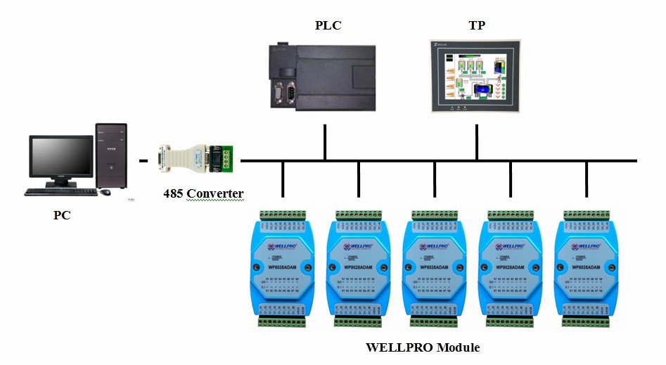
- Using RS485 MODBUS RTU communication standard. It can be netted with configuration software, PLC and industry touch pad
- Communication, input and output status LED
- Communication circuit designed for lightening protection and interference immunity
- Could be used for signal collection and control of Industrial field apparatus
- 3 Year's quality assurance for normal use
2. Specification
- Digital input: 16ch
- Working Temperature: -20 .. 70 degrees C
- External power supply: DC 9V-30V/2W
- Isolation protect: 1500VDC
- Installation method: Standard DIN slide rail or screw
- Dimension: 125x73x35mm
3. Interface definition
| Pin | Description |
|---|---|
| AVcc | External PSU positive terminal input |
| AGnd | External PSU negative terminal input |
| DI_01 | 1st way digital input |
| DI_02 | 2nd way digital input |
| DI_03 | 3rd way digital input |
| DI_04 | 4th way digital input |
| DI_05 | 5th way digital input |
| DI_06 | 6th way digital input |
| DI_07 | 7th way digital input |
| DI_08 | 8th way digital input |
| DI_09 | 9th way digital input |
| DI_10 | 10th way digital input |
| DI_11 | 11th way digital input |
| DI_12 | 12th way digital input |
| DI_13 | 13th way digital input |
| DI_14 | 14th way digital input |
| DI_15 | 15th way digital input |
| DI_16 | 16th way digital input |
| 485A | RS485 signal A+ |
| 485B | RS485 signal B- |
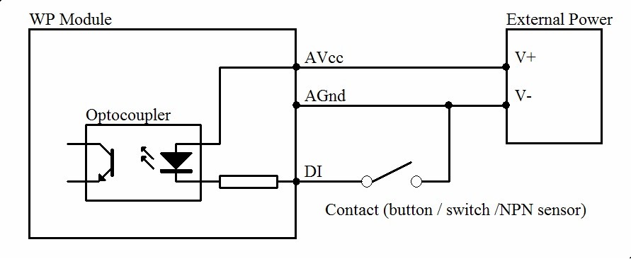
4. Digital input application diagram
5. Communication Instruction
5.1 Communication parameter (default setting): 9600,N,8,1
| Parameter | Description |
|---|---|
| 9600 | baud rate |
| N(no check) | check bit |
| 8 | data bit |
| 1 | stop bit |
5.2 Command for digital input collection:
Send: 01 02 00 00 00 10 79 C6 (example/hexadecimal)
| data | byte | data description | remark |
|---|---|---|---|
| 01 | 1 | module address | Address range 01-FE |
| 02 | 1 | function code | 02-read input bit |
| 0000 | 2 | input address (1x mode) | 0000-initial address of input bit |
| 0010 | 2 | read input length | 0010-read 16 input bit |
| 79C6 | 2 | CRC check code | CRC check code for all data |
Receive: 01 02 02 21 A0 A1 90 (example/hexadecimal)
| data | byte | data description | remark |
|---|---|---|---|
| 01 | 1 | module address | Address range 01-FE |
| 02 | 1 | function code | 02-read input bit |
| 02 | 1 | byte numbers | 02-read 2 byte length |
| 21A0 | 2 | read data | 21A0-read input bit status |
| A190 | 2 | RC check code | CRC check code for all data |
Converting reading data "21" to 2 hexadecimal results "0010 0001". From left to right, it represents the 8 digital input DI_08-DI_01.Converting reading data "A0" to 2 hexadecimal results "1010 0000". From left to right, it represents the 8 digital input DI_16-DI_09. Here it means DI_16,DI_14,DI_06 and DI_01 have input but others no.
5.3 Command for module address setting:
Send:00 06 00 64 00 01 08 04 (example/hexadecimal)
| data | byte | data description | remark |
|---|---|---|---|
| 00 | 1 | module address | 00-group sending |
| 06 | 1 | function code | 06-write single register |
| 0064 | 2 | register address (4x mode) | 0064-modify module address |
| 0001 | 2 | data writing | set new address for module, range 0001-00FE |
| 0804 | 2 | CRC check code | CRC check code for all data |
Receive:00 06 00 64 00 01 08 04 (example/hexadecimal)
This command means to send a code to a module, set the module address as 01, this setting could be saved when power off; default address of module is 01,each module address could be assigned separately when using multiple modules for network. Attentions is required that only one module could be used in 485 network when using multiple address sending, otherwise all the modules will share the same address in 485 network. When module receives correct command, it will make corresponding actions and send response back to the master. This is successful communication.
5.4 Command for communication parameter setting:
Send:01 06 00 65 00 02 18 14 (example/hexadecimal)
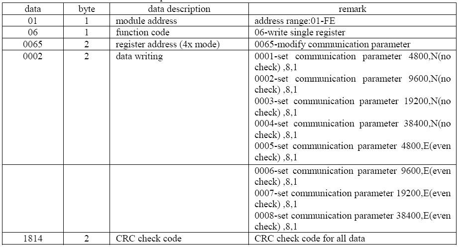
Receive:01 06 00 65 00 02 18 14 (example/hexadecimal)
This command means to send a code to the module and set the communication parameter as "9600, N (No check), 8, 1". This setting could be saved when power off. The default communication parameter is "9600, N (no check), 8, 1". Attention is required, when electing the correct communication parameter in communication setting and restarting the communication terminal, setting will be done. Normally, the lower of baud rate, the lower of the transaction speed but the higher of transaction stability. The opposite is also true. When module receives correct command, corresponding action will be taken and response will be sent back to the master. This is successful communication.
6. Indicator LED description
- When module powered on, Led is green.
- When module is under communication, LED is twinkling.
- When module receive correct command, LED is green.
- When module receive incorrect command or command for other modules, LED is red.
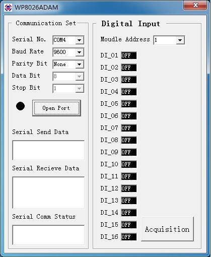
7. PC debugging instruction
This module provides software for parameter setting and function test. Please follow the steps below:
- Connect the module and computer using RS485 converter.
- Connect 12V or 24V power with module and power on. To avoid any unnecessary damage, please make sure the power positive and negative terminals are correctly connected before power on.
- Open the software, select the correct module number, you will see the window of function test or parameter setting.
- Set correct parameter, open communication interface.
- Select corresponding setting, collection and control items.
8. RS485 network diagram