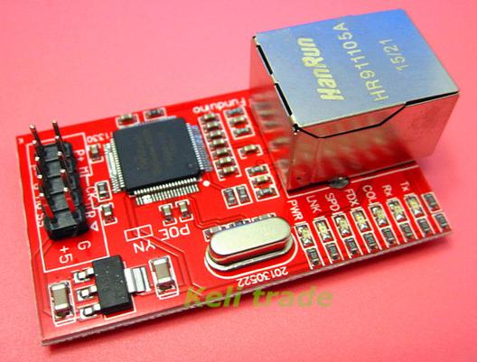
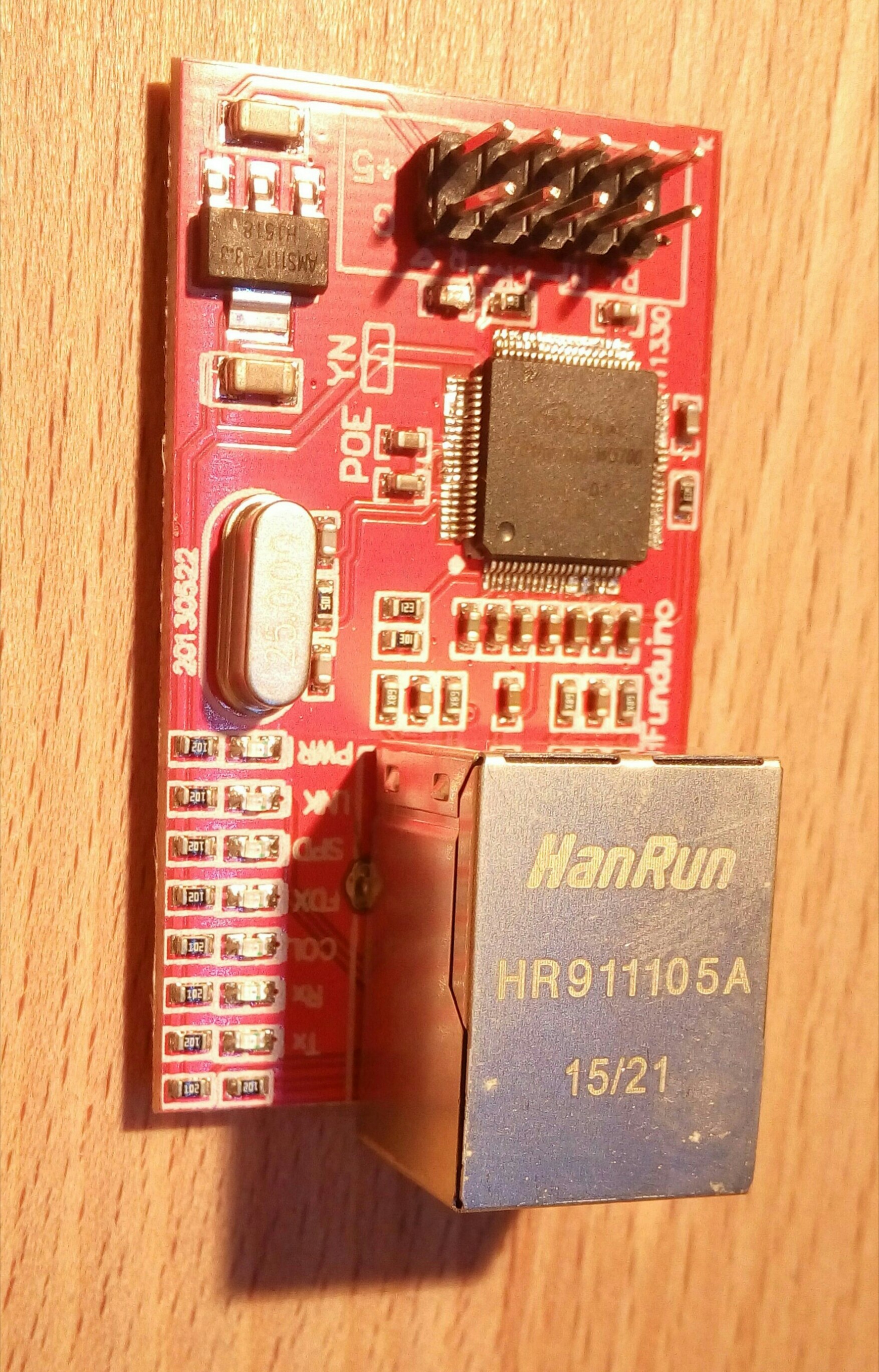
Arduino W5100 Ethernet Shield
- There is on-board voltage regulation, so you can use 5-12V VCC input. The signal pins support both 3.3V and 5V levels.
Connection to Arduino
- Pins 10,11,12 and 13 on an Arduino are used for the Ethernet Module as shown below.
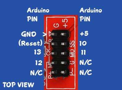
| PIN | Function | Arduino PIN | Suggested Color |
|---|---|---|---|
| 1 | GND | GND | BROWN |
| 2 | Vin 5V | +5V | RED |
| 3 | RESET | n/c | |
| 4 | SS or NSS (Slave Select) | 10 | ORANGE |
| 5 | SCK or CK (SPI Interface) | 13 | YELLOW |
| 6 | MOSI or MO (SPI Interface) | 11 | GREEN |
| 7 | MISO or MI (SPI Interface) | 12 | BLUE |
| 8,9,10 | No Connection | n/c | n/c |
The function of the LEDs
| PWR: | indicates that the module is powered |
|---|---|
| LINK: | indicates the presence of a network link and flashes when the shield transmits or receives data |
| FDX: | indicates that the network connection is full duplex |
| SPD: | indicates the presence of a 100 Mb/s network connection (as opposed to 10 Mb/s) |
| RX: | flashes when the shield receives data |
| TX: | flashes when the shield sends data |
| COL: | flashes when network collisions are detected |
Datasheet
Comments: