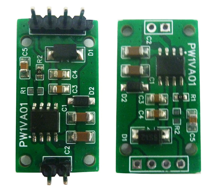
PW1VA01: 1-Channel PWM to 0-5V/10V PAC Module with GP8101
The GP8101 is made by “Guestgood Electronic Components”. At the time of writing this, their website at www.guestgood.com is down.
An alternative GP8101 is from “Linearin Technology Corporation” (http://en.linearin.com/). The chip from Linearin has a maximum power supply of 15V, compared to 40V for the chip from Guestgood.
PAC stands for “PWM to Analog Converter”.
Functions
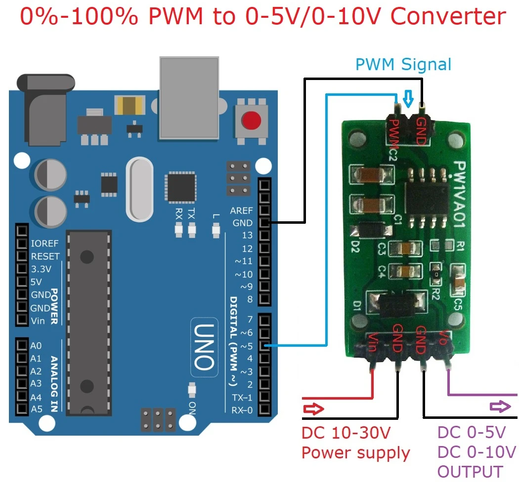
The PW1VA01 module is a 1-channel DAC module with PWM communication, a resolution of 8-bit, and 0.1% output voltage linearity error, capable of generating analog voltage outputs of 0-10V or 0-5V. The 0-10V or 0-5V voltage output is a standard driving method. It can be widely used in automation control scenarios such as lighting adjustment, frequency converters, valve regulation, pump control, etc. This product can drive a variety of 0-10V or 0-5V controlled devices available in the market through Arduino programming.
The PWM signal drive allows the module to be controlled by MCU digital ports, providing a simple and convenient usage.
Features
- Support 3.3V-5V power supply.
- Output voltage linearity error of 0.1%.
- Two channels of voltage output, either 0-5V or 0-10V, enabling connection and control of standard analog voltage devices.
- Gravity interface, PWM communication, Arduino control, suitable for program automation control.
- PWM signals can be utilized to drive the module, enabling it to be controlled simply by the digital port of the MCU.
Specification
- Chip Type: GP8101
- PWM input level Voltage: 3.3V-5V
- Output Voltage: 0-5V or 0-10V
- Number of Channels: 1 channel
- Communication Method: PWM
- Resolution: 8-bit
- Value Range: 0 - 255 corresponding to 0-5V or 0-10V
- Output voltage linearity error: 0.1%
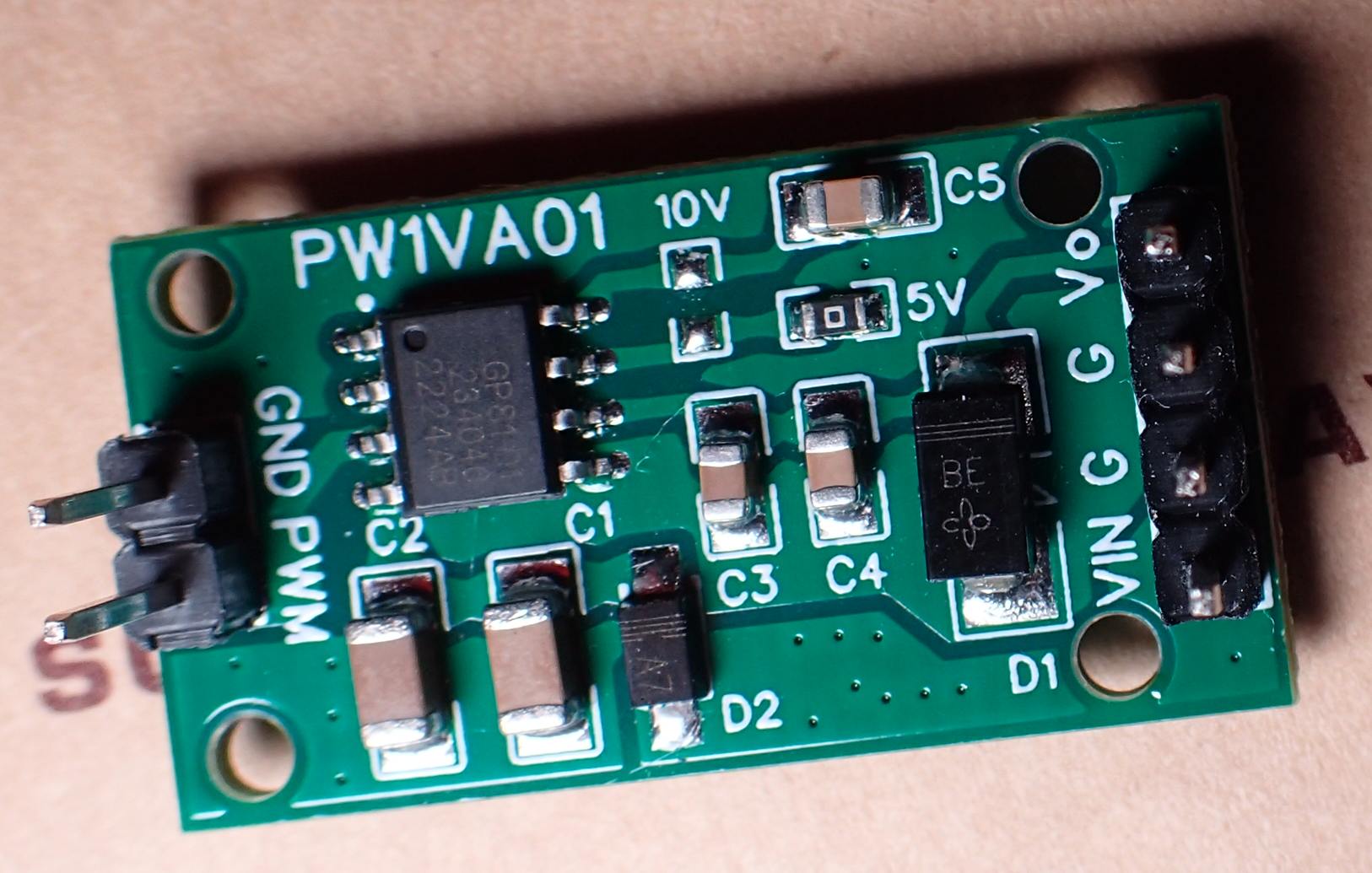
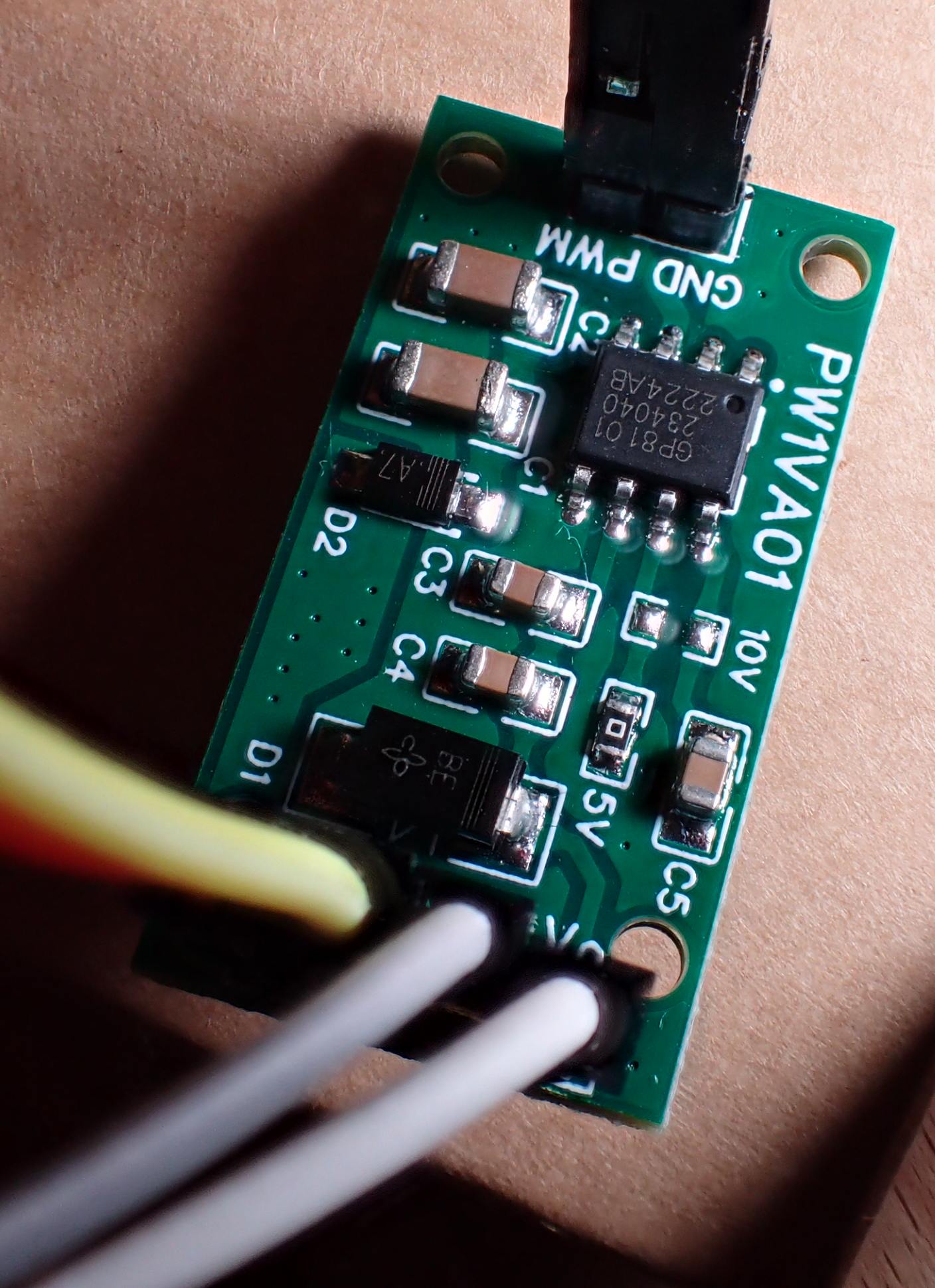
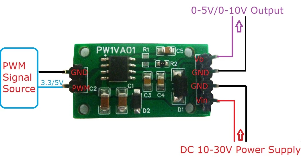
Pin definition
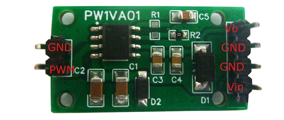
| Pin Name | Description |
|---|---|
| Vin | Input power + (DC 10-30V) |
| GND | Input power - |
| GND | Output - |
| Vo | Output + (DC 0-5V/0-10V) |
| PWM | Input PWM signal + (3-5V) |
| GND | Input PWM signal - |
All the GND pins are connected to each other!
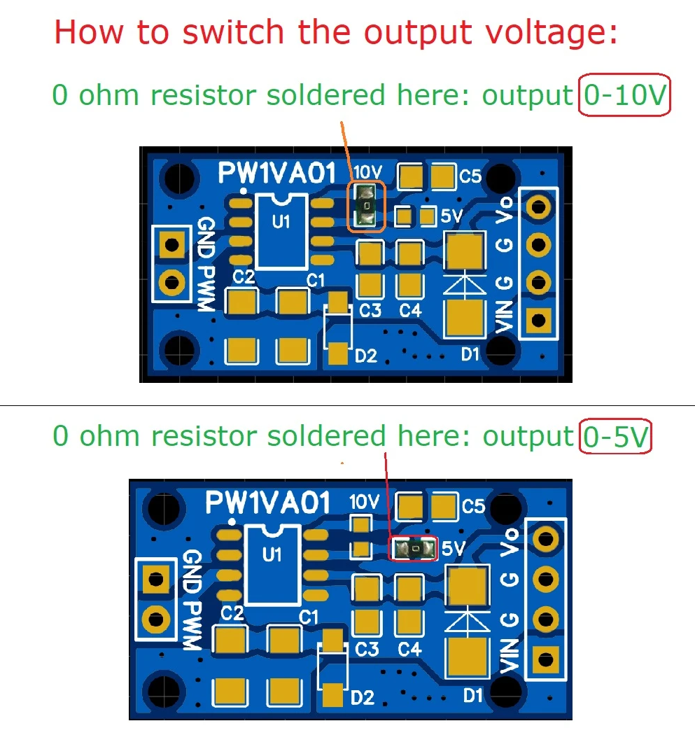
Configuration
The module can be configured for 0-10V output or 0-5V output by soldering a jumper.
Usage
Software library
This Arduino library supports a whole series of converter chips, but for the GP8101 it does not add much value:
https://github.com/DFRobot/DFRobot_GP8XXX
User comments
User 1
From what I found from my testing, it has strong advantages over the other typical modules:
- the output is absolutely linear and also frequency and supply voltage independent,
- doesn’t need fiddling with an adjustment potentiometer,
- it can achieve the full 10V on the output, even if the supply is a bit below 12V (so it works fine with the 12V-ish output of my VFD).
User 2
Slight downside: The module from above doesn’t have an optocoupler on it, so one needs to add one separately.
User 3
The GP8101 PWM to Analogue IC data sheet says that it accepts a PWM frequency from 50Hz to 50kHz. I found that at higher frequencies there was significant non linearity so I’m running it down at 10 - 100Hz from memory.
Datasheets
Datasheet GP8101/GP8101M Guestgood
Datasheet GP8101/GP8101M Linearin
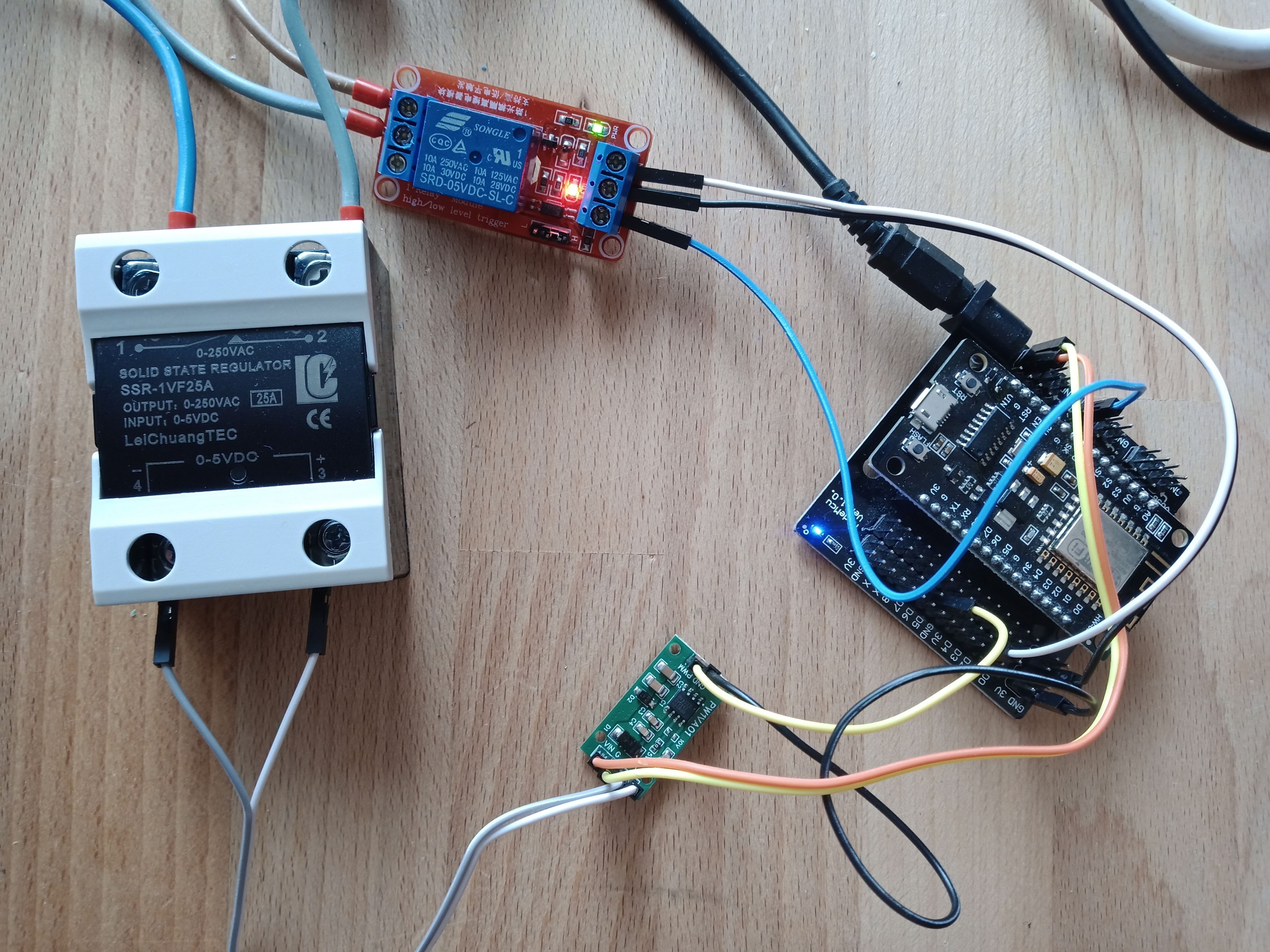
Experiment with ESP8266 NodeMCU and Tasmota PWM
I flashed a NodeMCU with Tasmota, connected D5 to the GP8101 module, and set the Tasmota pin to “PWM”. The Tasmota webinterface allows now setting the output pin from 0% to 100% in 1% steps. I measured the output voltage:
| PWM (%) | Voltage (V) |
|---|---|
| 0 | 0.03 |
| 10 | 0.06 |
| 20 | 0.09 |
| 30 | 0.23 |
| 40 | 0.44 |
| 50 | 0.80 |
| 60 | 1.25 |
| 70 | 1.92 |
| 80 | 2.74 |
| 90 | 3.79 |
| 100 | 5.00 |
The measurements are equal for the PWMFrequency = 40 Hz and the Tasmota default of 977 Hz.
This is not linear at all - caused by the Tasmota setting “ledtable” - see below.
When using the output voltage to control a Triac module with 0-5V input, I succeeded in regulating a 1000W heater by setting the dimmer in the UI to the value in the first column:
| Dimmer (%) | Power (W) |
|---|---|
| 0 | 0 |
| 77 | 100 |
| 80 | 200 |
| 83 | 300 |
| 85 | 400 |
| 87 | 500 |
| 89 | 600 |
| 90 | 700 |
| 92 | 800 |
| 94 | 900 |
| 100 | 1000 |
Corrections on this Experiment with ESP8266 NodeMCU and Tasmota PWM
Later I figured that the Tasmota software has a setting “LEDtable” which causes the non-linearity. Once I set “ledtable = 0”, the curve was perfectly linear. One of the advertised strong properties of the GP8101 is its linearity - well, that is correct! It also has a correct output when the PWM is at 0% (0V) and at 100% (5V in the case I tested).