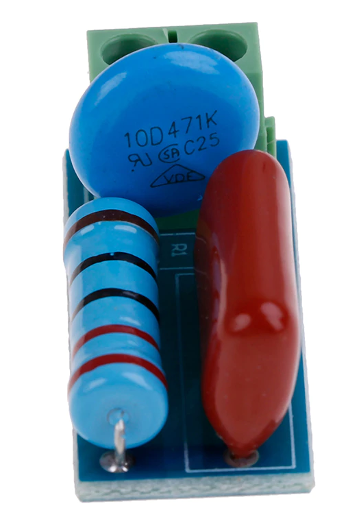
Varistor 10D471
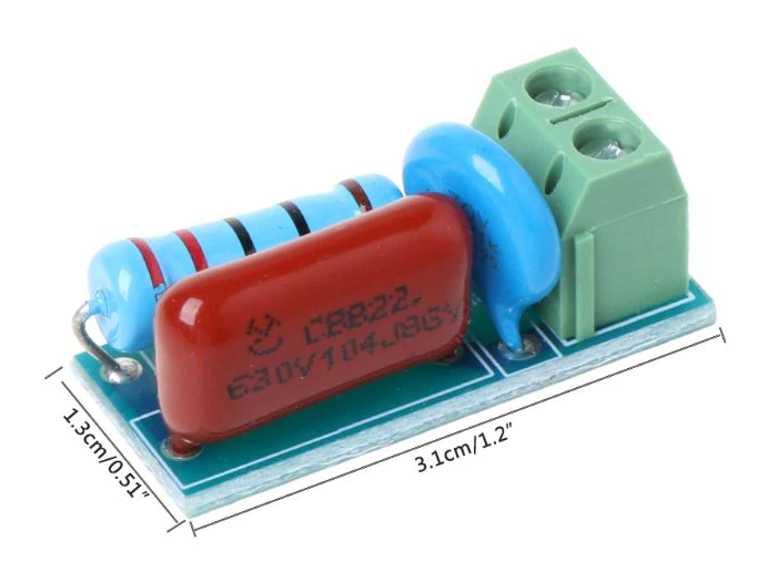
Capacitor 100nF 630V
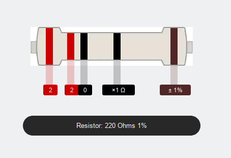
Resistor 220 Ohms 1%
Surge Suppression theory
Taken from Omron_FAQ.
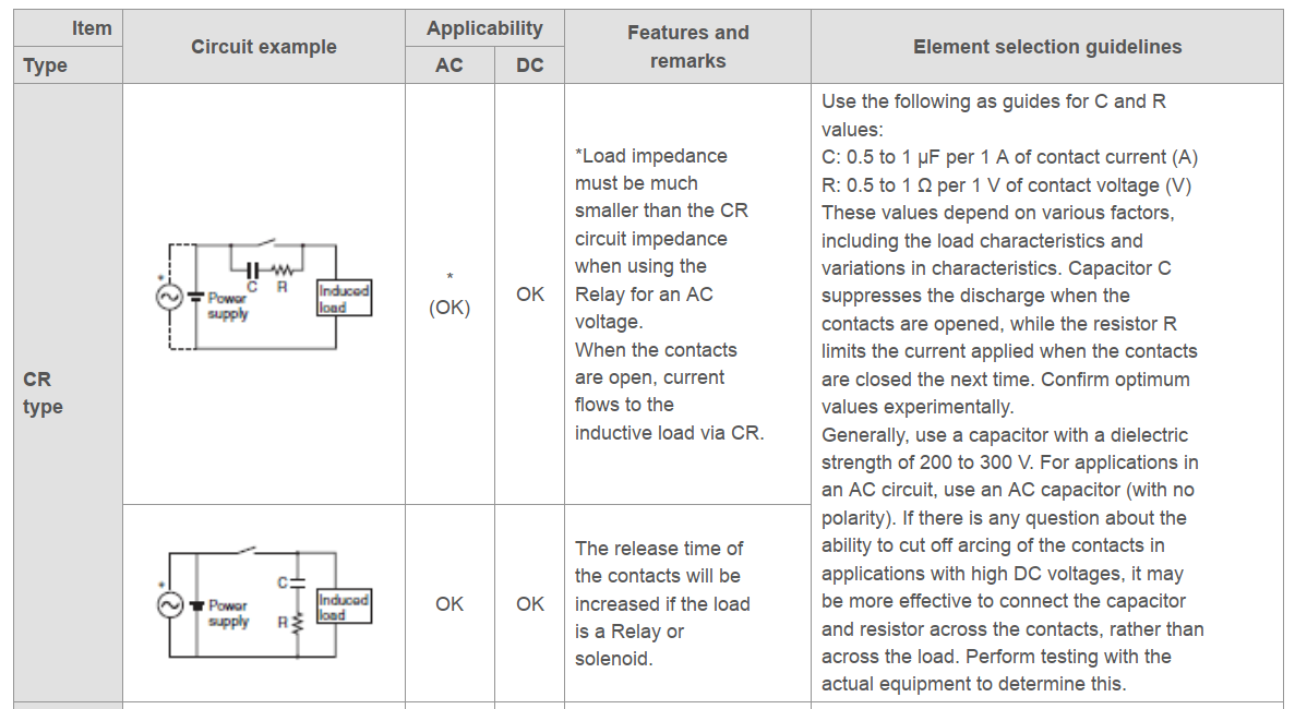
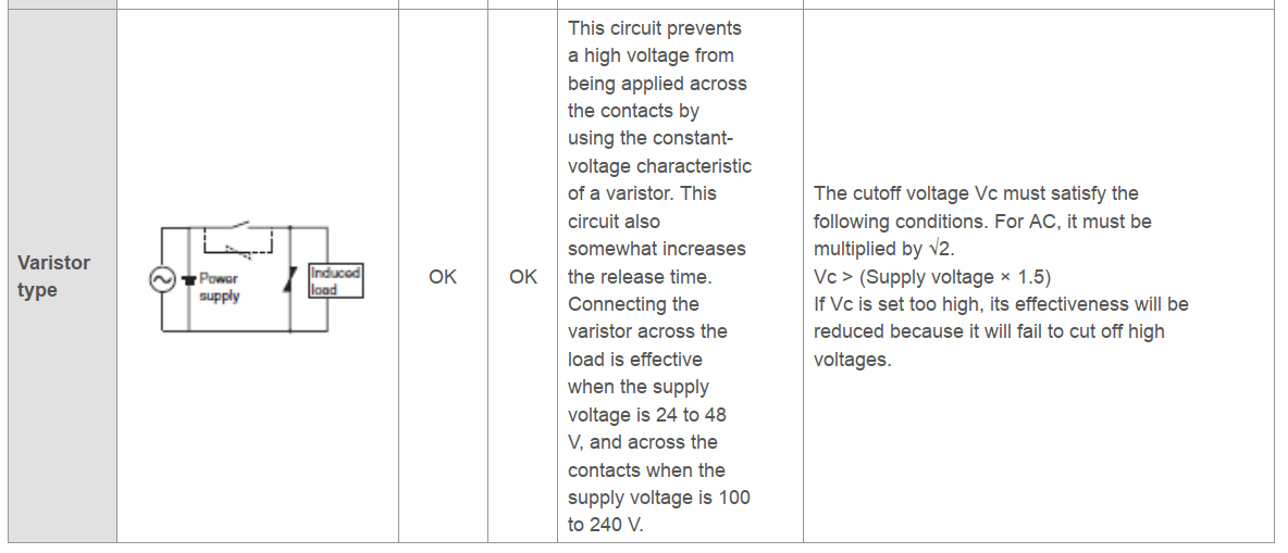
So, for an inductive load on AC, we should use the second circuit for the RC and the third one for the varistor, i.e. in both cases parallel with the inductive load, and NOT parallel with the switch.
Supplier information
Module features
The RC snubber circuit, also called the RC snubber circuit, is a circuit structure in which a resistor is connected in series with a capacitor and connected in parallel with the switching device to improve the voltage and current waveforms that the electronic power device is subjected to when it is turned on and off. The RC absorption circuit module can prevent the induced electromotive force generated by the inductive load from being turned on and off, causing damage to the switching devices such as relays and thyristors, preventing electromagnetic interference and increasing the anti-interference ability of the single chip microcomputer.
Product parameters
- Suitable for AC or DC 5~400V inductive load (less than 1000W load) to protect relay contacts or thyristors.
- RC absorption loop, absorbing the induced electromotive force of the inductive load
- There is a varistor to prevent excessive voltage fluctuations and excessive current, causing the relay contacts to stick.
- Provide the anti-interference ability of the circuit.
- Use crimp terminals to make wiring more convenient.
Board function description
Instructions for use: This module is suitable for circuits with inductive loads and switching devices (such as relays and thyristors). When used, the two interfaces of the module are connected to the two contacts of the relay (such as relay and common and normally open), or it is connected in parallel with the thyristor to avoid damage to the relay and thyristor induced by the electromotive force.
| Beware: | The above contradicts the Omron FAQ! |
|---|
See also Snubber.pdf.