When the lower floor of the house had to undergo major reconstruction, I developed a domotica system to couple push buttons in the wall to the lights. The intention was that all behaviour could be programmed in software, with possibilities to make smart behaviour. Also, I wanted to wire the buttons with thin wires, so that we could have a lot of buttons, without increasing the price and work too much. The house wiring is designed in a way that the whole domotica system can be replaced by an Eltako based system with pulse relays.
Used components
- ControllinoMega
- InputIsolationBoard
- WellPro_WP8026ADAM
- Domoticz on Synology or on Raspberry Pi
Design principles
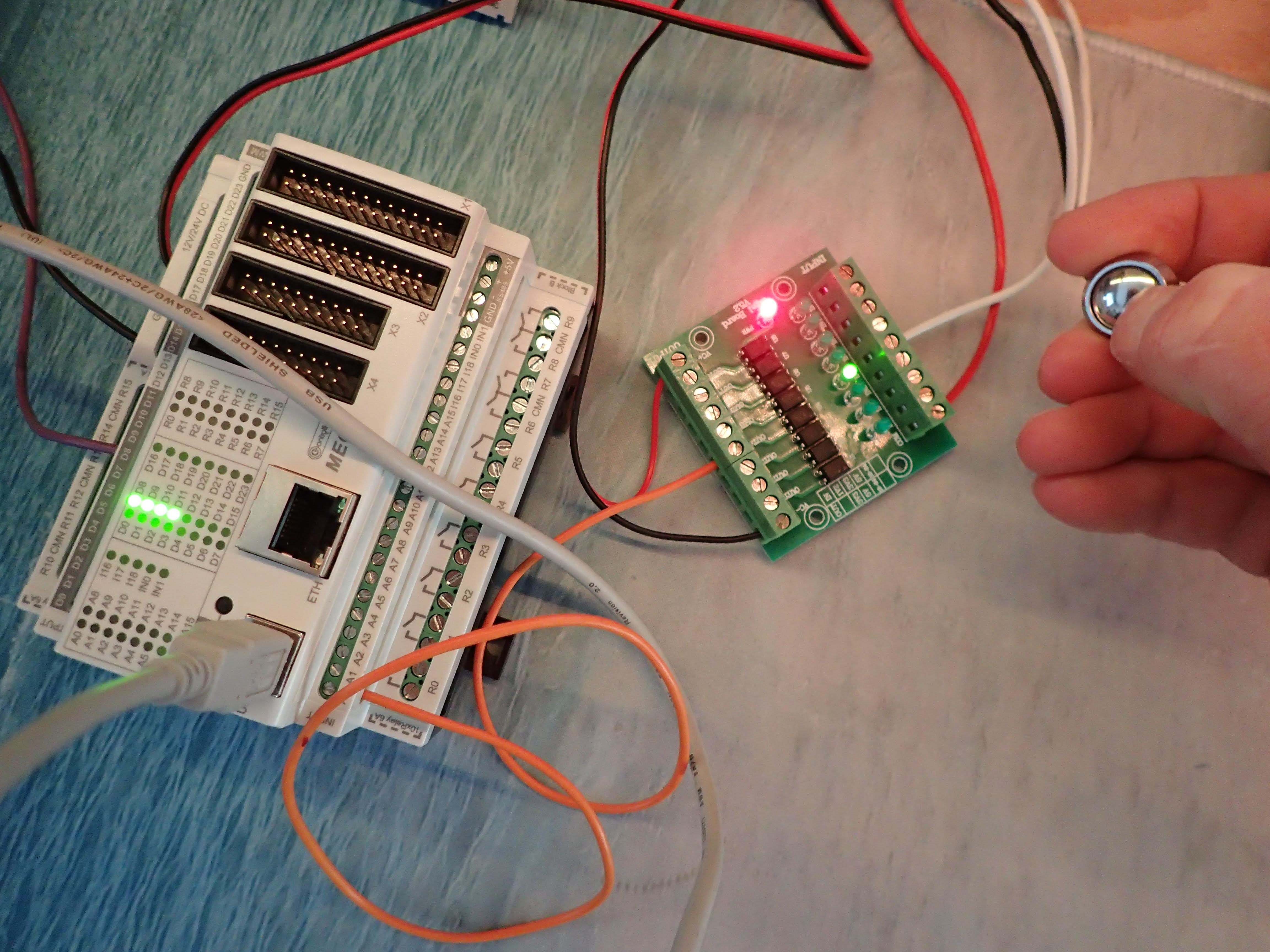
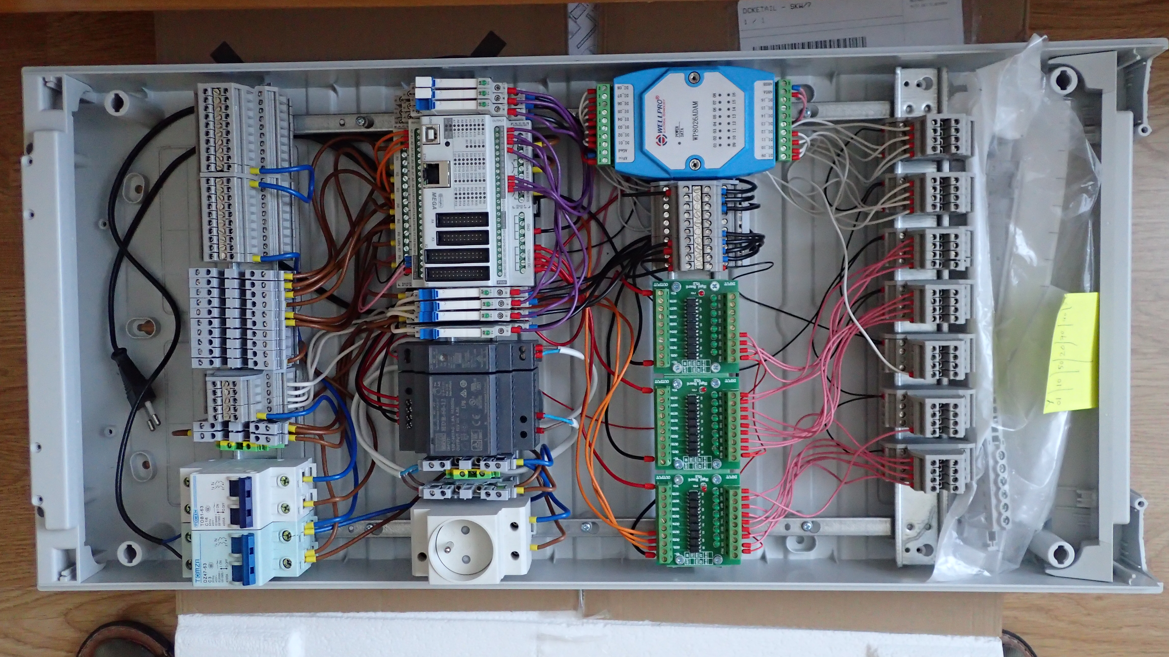
The system is build around a Controllino Mega, which is an industry-grade PLC with 100% Arduino compatibility. This PLC has many inputs, which are used for the push buttons in the walls of the house and many outputs, that switch the lights in the house.
Some of the lights are switched by means of the relais built in in the Controllino, others use external relais.
The RS485 port of the Controllino is connected to a Wellpro WP8026ADAM, which adds 16 digital inputs for push buttons.
Since the long wires to the push buttons in the walls of the house may pick up disturbances for which the system may be sensitive, they are all galvanically seperated by optocouplers and a seperate power supply.
The ethernet port of the Controllino is connected to the home network, which allows the Controllino to cooperate with the home automation controller.
The software in the Controllino includes the MySensors Arduino library which handles the protocol between PLC and the home automation controller Domoticz. This implementation does not make use of the MySensors radio network. In MySensors terminology, the Controllino combines a gateway with sensors (the light switches) and actuators (the light relays) on board.
Domoticz is an application installed on a home server, originally on a NAS (Synology), later on a Raspberry Pi, currently in a container on a Proxmox server, which logs events, and implements all smart behaviour.
The Controllino system is designed so that it is able to operate without network; this means that the buttons will operate the correct lights. However, smart behaviour like switching a light off after a certain time-out, is handled by Domoticz.
The software in the Controllino makes use of State Machines to organise the timing and multi-tasking. The Automaton library is a Reactive State Machine Framework for Arduino.
Wiring
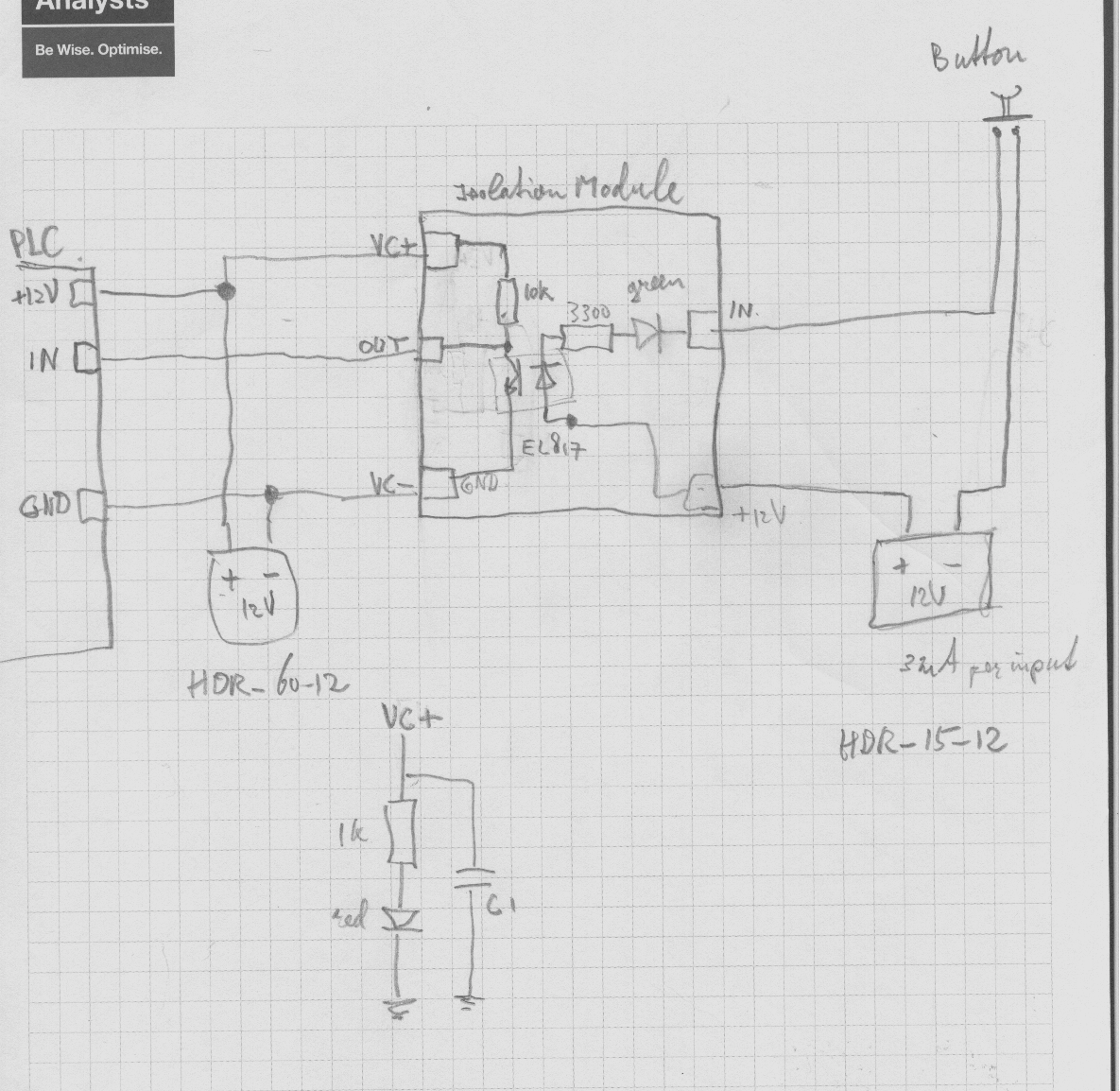
Button inputs
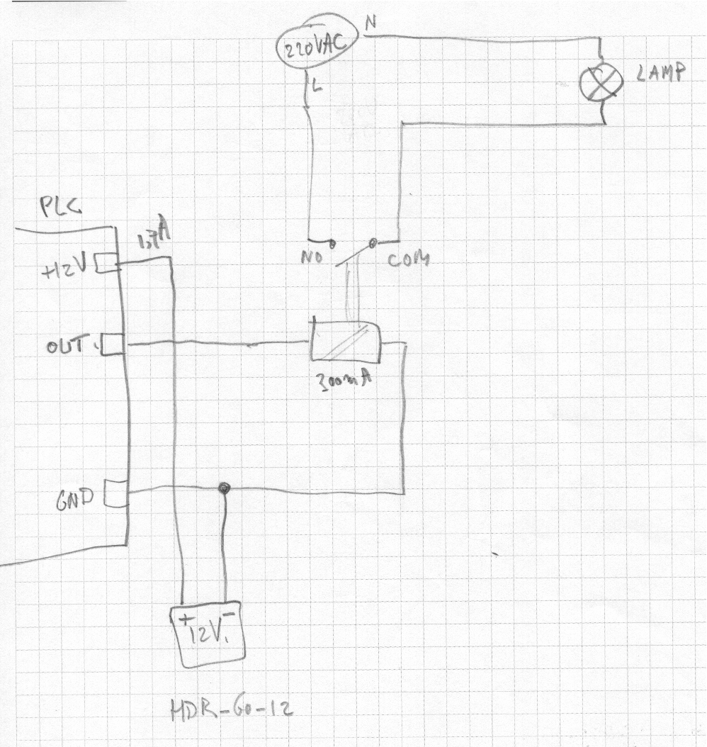
External relays
Prevention of rush-in current
See https://michiel.vanderwulp.be/domotica/Nodes/LEDstripAnd7Spots/#the-statemachine-riclim
Construction
Prepared for mounting
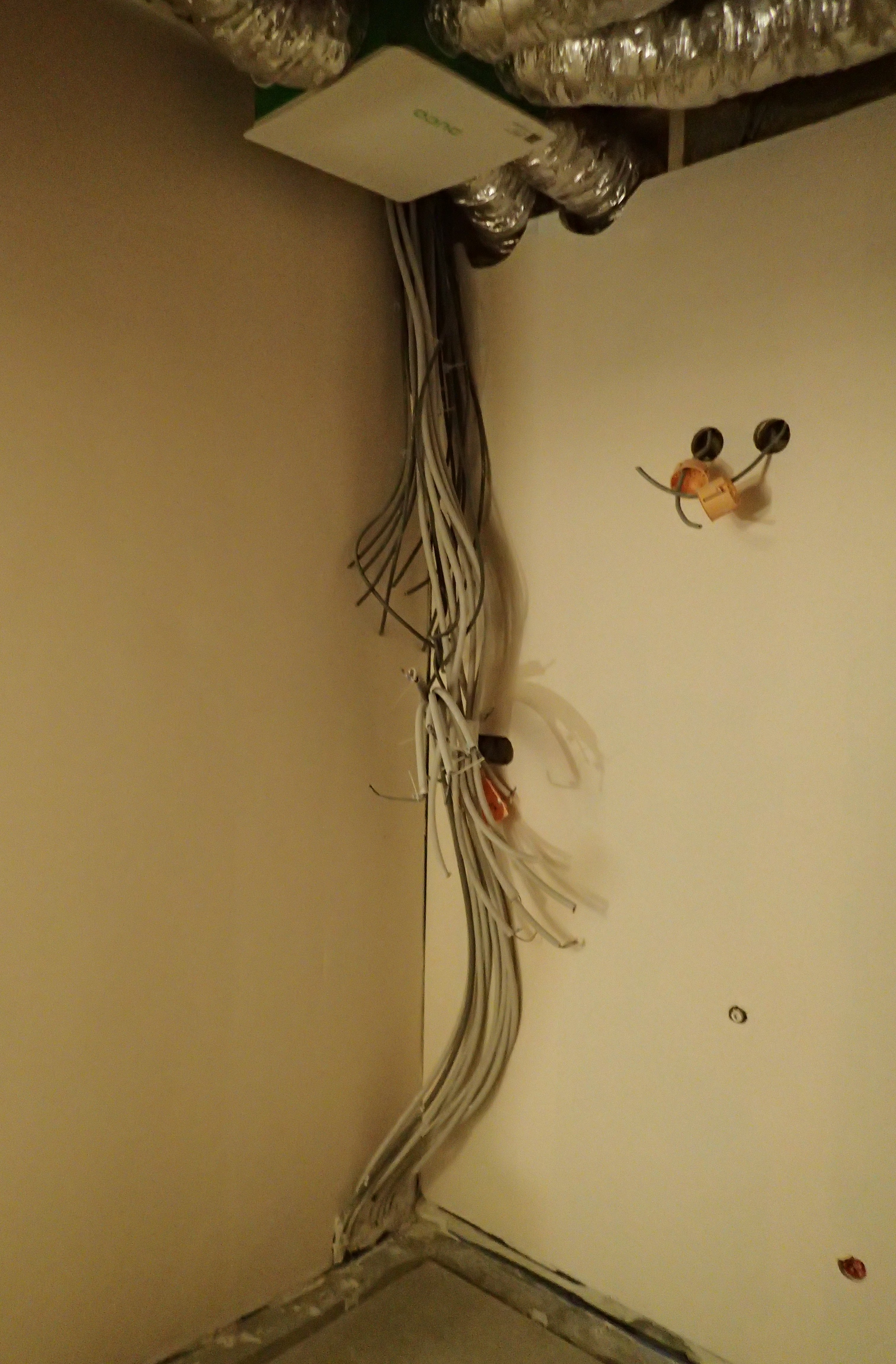
Before mounting
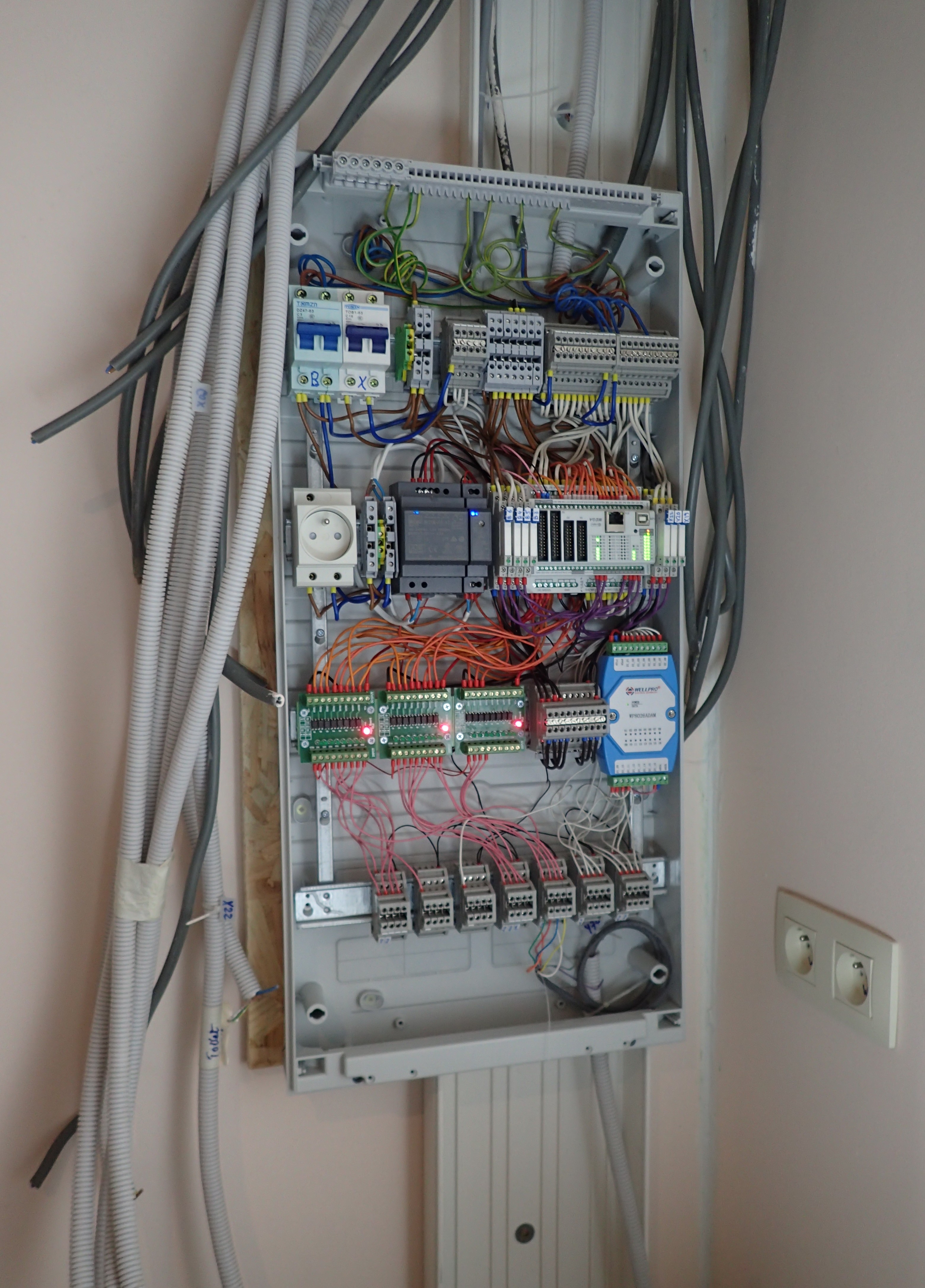
Mounted, testing the first connection
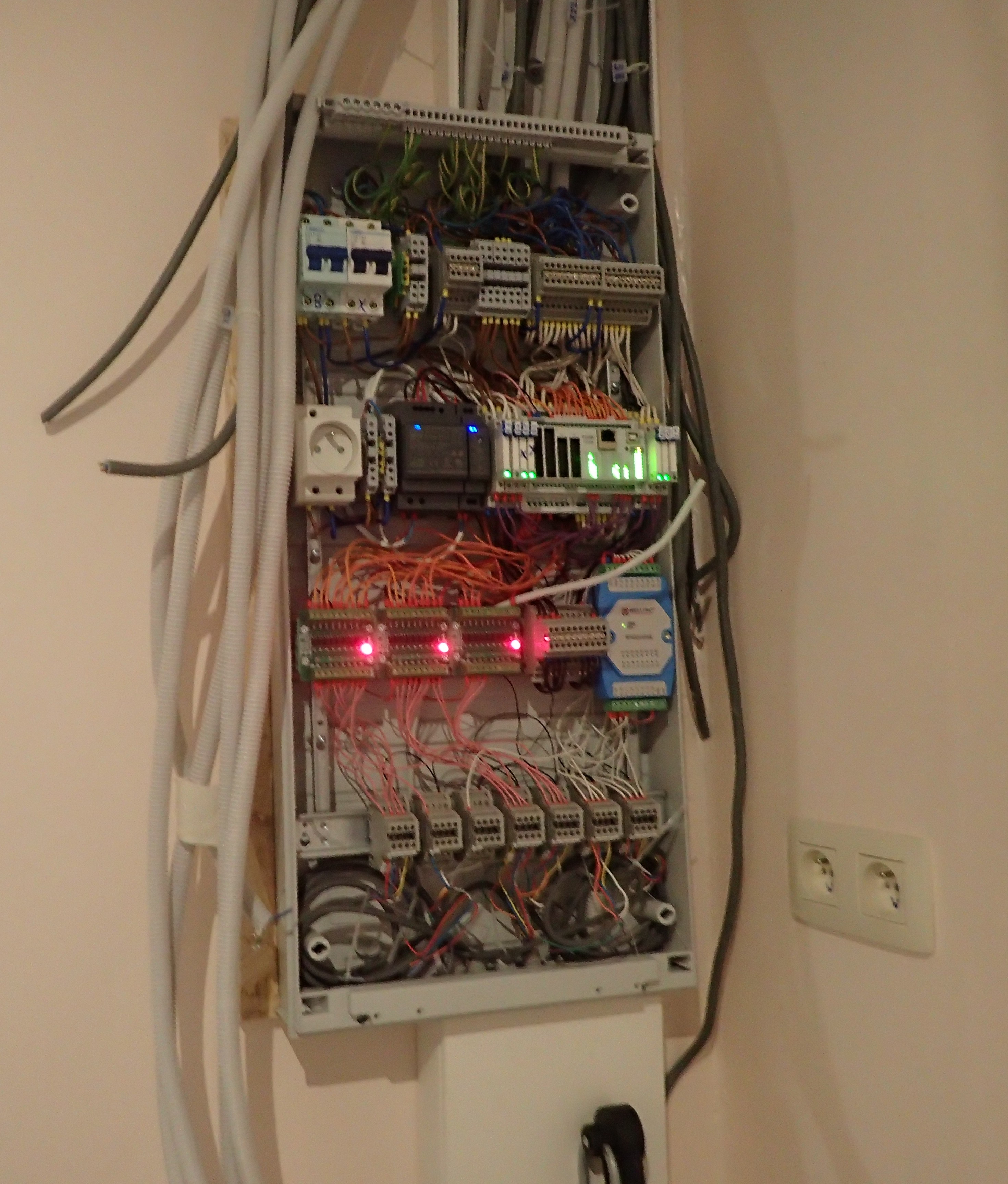
Partly connected
Software code of the Controllino
The Arduino code handles all the Buttons and Relais, hence the abbreviation 'butenrel'. The system implements a MySensors gataway, hence the foldername 'msgwbutenrel'.
All code is in the Gitlab project: msgwbutenrel
Programming the Controllino
Debugging the Controllino is possible by connecting it to a PC with an USB cable, and using the Arduino IDE with the following parameters:
- baud rate 115200
- board: Controllino Mega
Network
Using DHCP for IP assignment has the downside that the Arduino code in the ".ino" file is not even reached when the ethernet cable is not plugged in. Hence the system has static IP: 10.0.0.10.
MySensors gateway
The mysensors code is based on https://github.com/mysensors/MySensors/tree/development/examples/GatewayW5100. It implements a gataway, and registers all relais as actuator nodes. The buttons are not known to the MySensors system.
The gateway always has node id 0.
State machine Relais
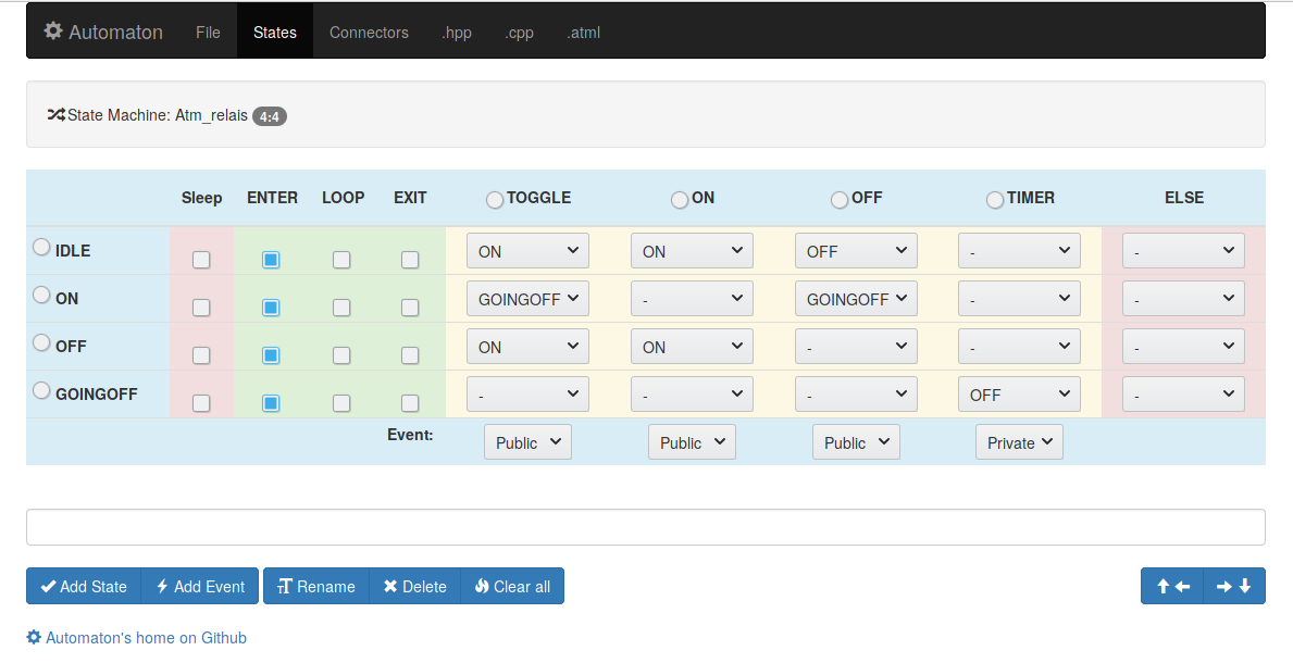
This node uses one automaton per relais to remember its state, and to make sure that a relais is not switched back on immediately after switching it off. This to prevent excessive rush-in currents which melds the relay contacts together.
The system waits a few ms between switching on different relays. This will prevent simultanous rush-in current for all relays.
Specific relais with a heavy rush-in current may wait extra long before switching on a 2nd time again to prevent the relais contacts to fuse.
Rush-in currents are highest for the 12V power supply modules that are used for the LED lights.
State machine NButton
This node uses one automaton per button for debouncing.
Only the relais states are made visible with the MySensors protocol, not the buttons. The relais can be operated by the MySensors protocol.
State machine Modbus
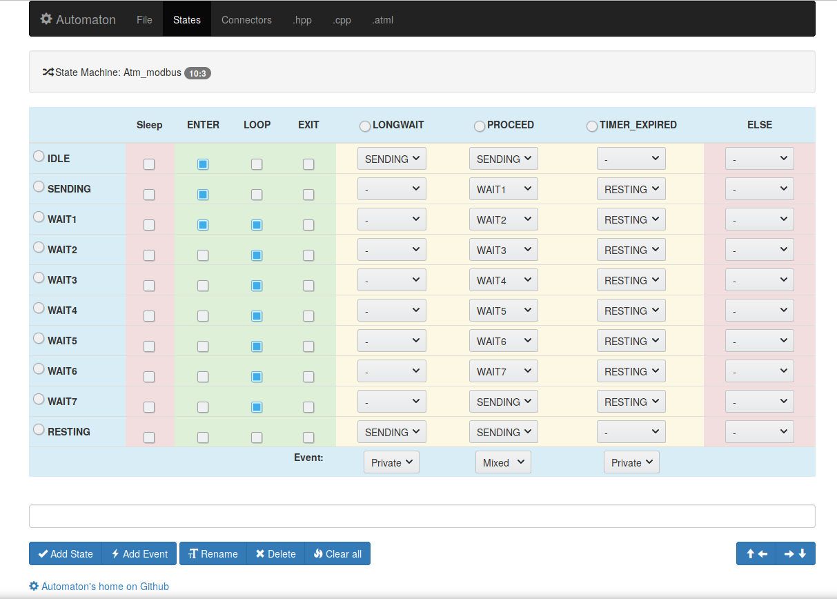
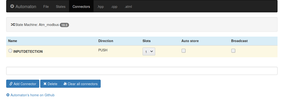
This state machine organises the communication in the Modbus protocol with the Wellpro WP8026ADAM.
Libraries, API documentation and Debug
See the following links:
| Description | Link |
|---|---|
| Controllino | https://controllino.com/ |
| MySensors Serial API | https://www.mysensors.org/download/serial_api_20 |
| MySensors Debug explanation | https://www.mysensors.org/build/debug |
| MySensors Debug detailed encoding | https://ci.mysensors.org/job/Verifiers/job/MySensors/branch/development/Doxygen_HTML/group__MyTransportgrp.html#details |
| Automaton | https://github.com/tinkerspy/Automaton |
| Automaton tutorial | https://github.com/tinkerspy/Automaton/wiki/Machine-building-tutorial |
| Automaton machine template editor | http://wolkendek.nl/atm/ |
| Mysensors - Automaton | https://forum.mysensors.org/topic/9336/using-state-machines-for-mysensors-sketch |
| Domoticz | https://www.domoticz.com/ |