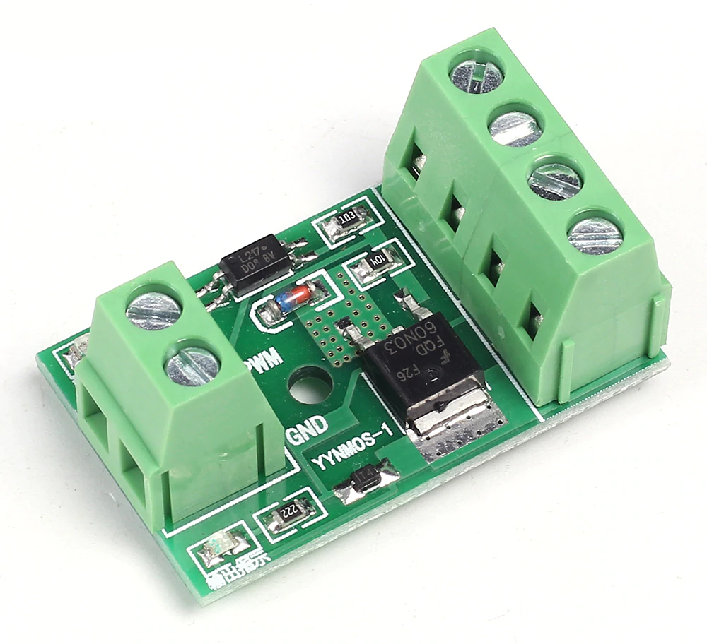
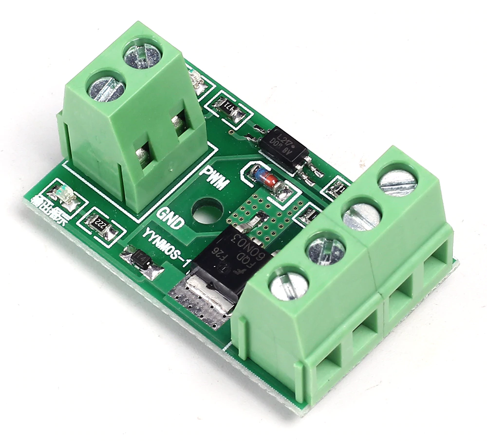
The YYNMOS-1
Supplier description
- Model: YYNMOS-1
- Input and output are completely isolated
- Input Signal: 3-20V PWM signal
- Output Capacity: DC 3.7-27V, and the current is below 10A
- PWM Frequency: 0-20KHz
Application
The output port can control high power devices, including inductive loads, such as motors, lamps, LED lamp strings, DC motors, micro water pumps, electromagnet valves; it can input PWM to control motor rotate speed and the brightness of a lamp.
The YYNMOS-1 module is described here and has one channel. There exists also a YYNMOS-4 module, which is a four-channel version.
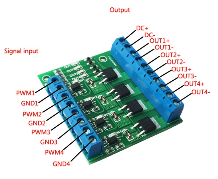
The YYNMOS-4
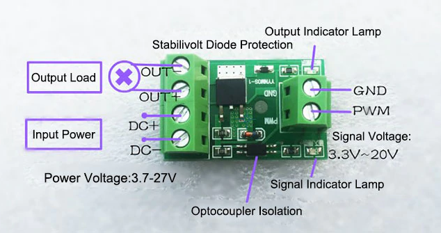
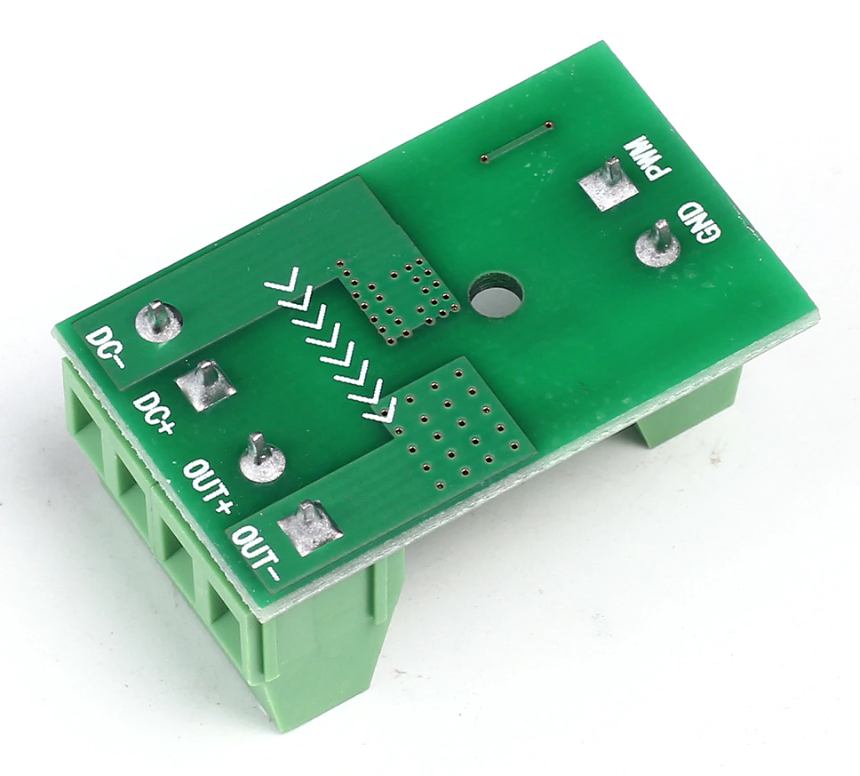
Interface Introduction
| Pin | Specification |
|---|---|
| DC+ | The positive pole of the device's DC power supply |
| DC- | The negative pole of the device's DC power supply |
| PWM | Signal input positive terminal (connects to MCU IO ports, PLC interface) |
| GND | signal input negative terminal |
| OUT+ | Positive output terminal (connects to the positive pole of the device) |
| OUT- | Negative output terminal (connects to the negative pole of the device) |
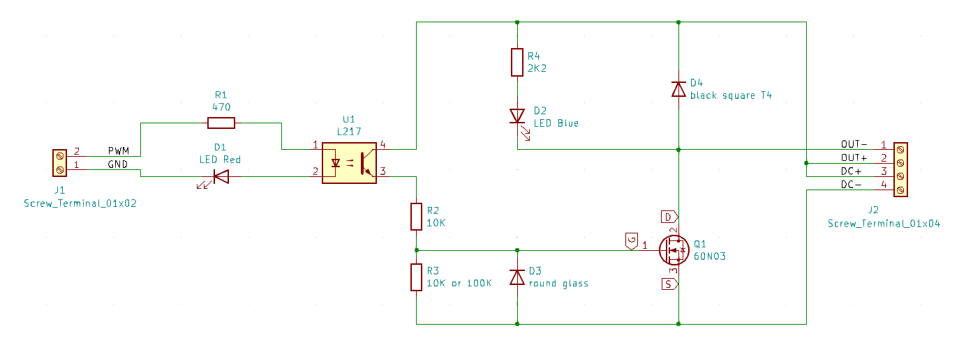
Reverse engineered schema of the module.
About D4: The square black diode is probably a 1N4148WT. It is marked "T4". This fly-back diode protects the other components against reverse voltage spikes due to an inductive load.
About D3: The glass diode is probably a ZMM5248B-7, which is a 18V Zener diode. It protects the gate of the FET against negative voltages and also against positive voltages above 18V. According to the 60N03 datasheet, the absolute maximum rating of the Gate-Source voltage is 20V, so hence the zener value of 18V.
About R1: This resistor limits the current through the LED in the opto-coupler. The module in the picture has a value of 470Ω, the one I bought has 2K2. Due to this high value, the module does not work when connected to a NodeMCU pin, which works with 3.3 Volt. Initially, I tried to get it working by shorting the LED D1, but that did not help enough. So, I replaced the resistor with one of 470 Ohm, and that solved the problem.
About LED D1 and LED D2: In one of the modules I bought, LED D1 (at the input) is a blue LED, and LED D 2 (at the output) was a red LED. Due to the blue LED, the input did not work with a 3.3V nput signal, it works with a 5V input. This can be explained by the forward voltage of the LED: for a blue one it is 2.7V, and for a red one 1.9V. Would they have switched the colours, the module would have worked with a standard 3.3V input signal! The correct configuration is shown in the schema above.
About R3: The module in the picture has a value of 100K, the one I bought has 10K (which is not so good). If R2 and R3 are 10K, then the voltage on the gate is maximum half the power-supply voltage. Since the gate threshold voltage may be as high as 3V (see datasheet), the circuit may fail if your power supply is 5V. Hence it is much better to have R3 = 100K, in which case the gate will get maximum 100/110 = 91% of the power supply voltage. But maybe the value of R3 = 10K is needed to make the module work with higher frequencies - a lower R3 will discharge the parasitic capacity of the gate quicker. And also, if you want to control a load powered by 24V, then you will need a lower R3 like 10K, since the gate voltage may never get over 18V. So, it all depends on your application.
Make the inputs work with a 3.3V signal
The module is specified for a 3 to 20V PWM signal.
As stated above, some modules have the wrong components in the wrong place, which causes the modules not to function correctly with 3.3V input signals.
- If the R1 value is above 470 Ohm, you better replace it.
- If the input LED is blue, the forward voltage of this LED is too high. The forward voltage over de LED in the opto-coupler is 1.2V, and over the blue LED is 2.7V. Together that is 3.9V! So, they won't light. In this case, the best advise is to bridge the LEDs with a wire. Experiments show, that shorting the input LEDs makes the FET switch on from an input signal as low as 1V (with R1 = 470Ohm).
Product application example
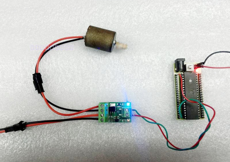
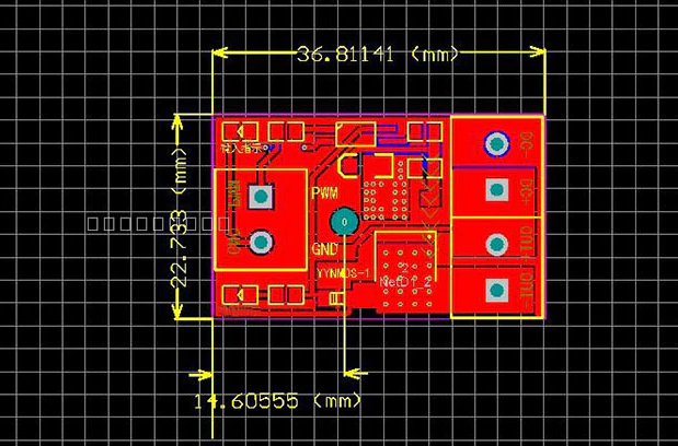
Layout and connections