Sensor choice
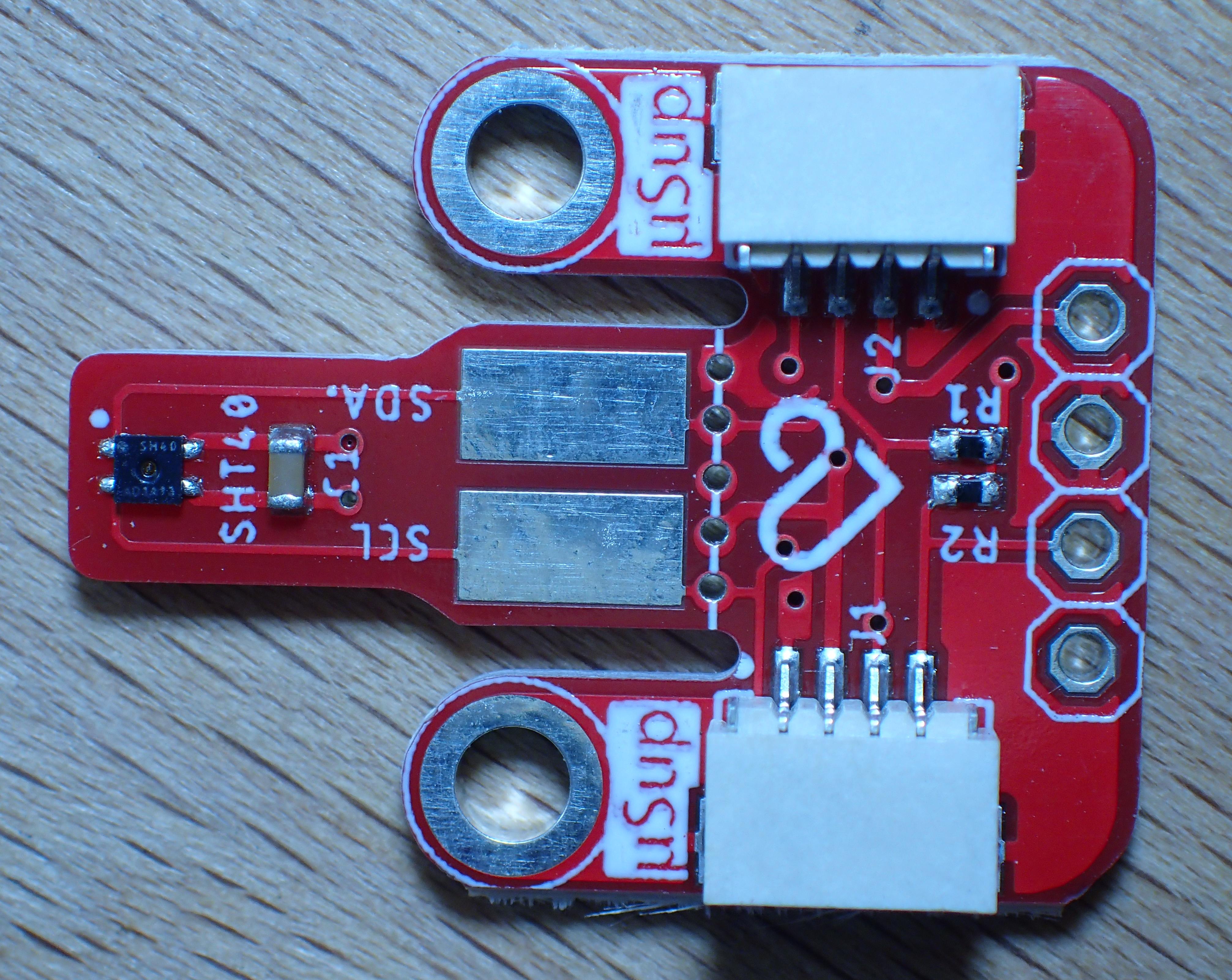
The sensor is a mass-produced standard module available worldwide, intended for QWIIC and STEMMA applications. The advantage of this module is that it can easily be cut to a very small size.
How to connect a temperature sensor
A temperature sensor like the SHT40 can be connected to the I²C bus already used on the module. Other I²C sensors would work also, e.g. the Si7021.
| GPIO | Device |
|---|---|
| GPIO19 | I2C SDA |
| GPIO45 | I2C SCL |
Sensor power supply
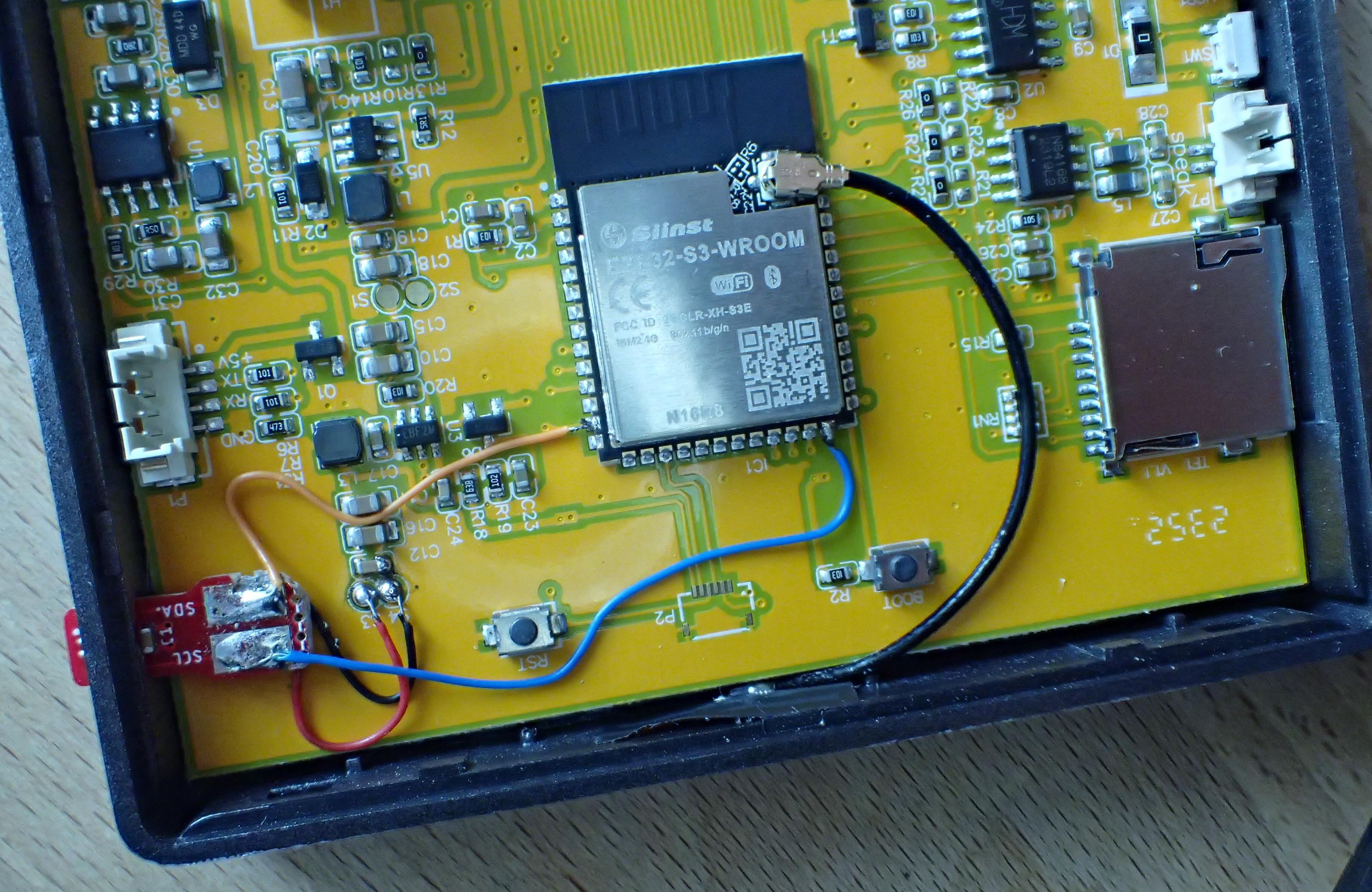
To connect the wires of the sensor, you can use the test-points on the PCB:
| Testpoint | is connected to |
|---|---|
| S1 | +5V |
| S2 | GND |
| S3 | +3.2V |
| S4 | GND |
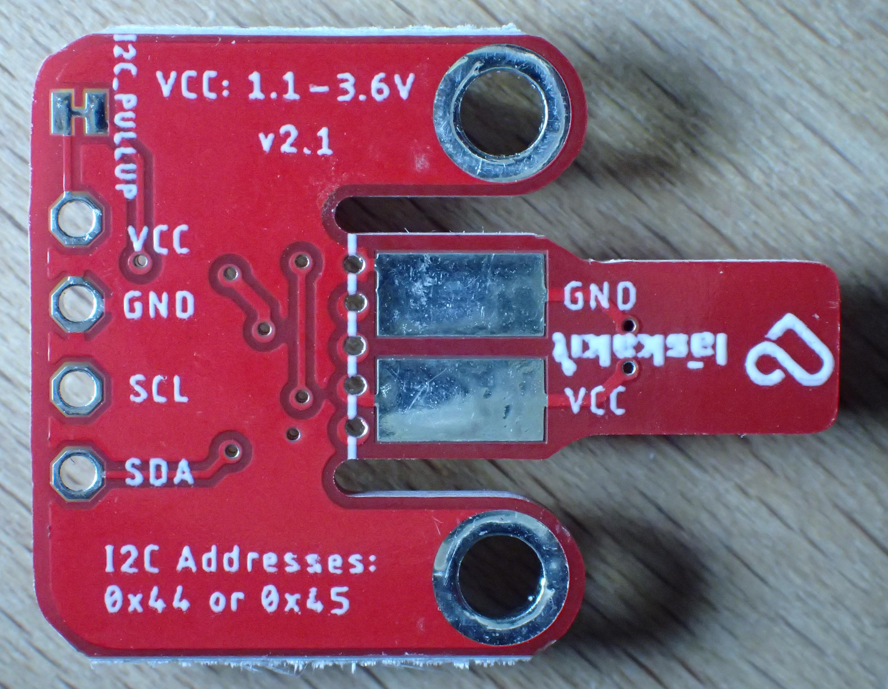
The SHT40 and Si7021 need 3.3 Volt.
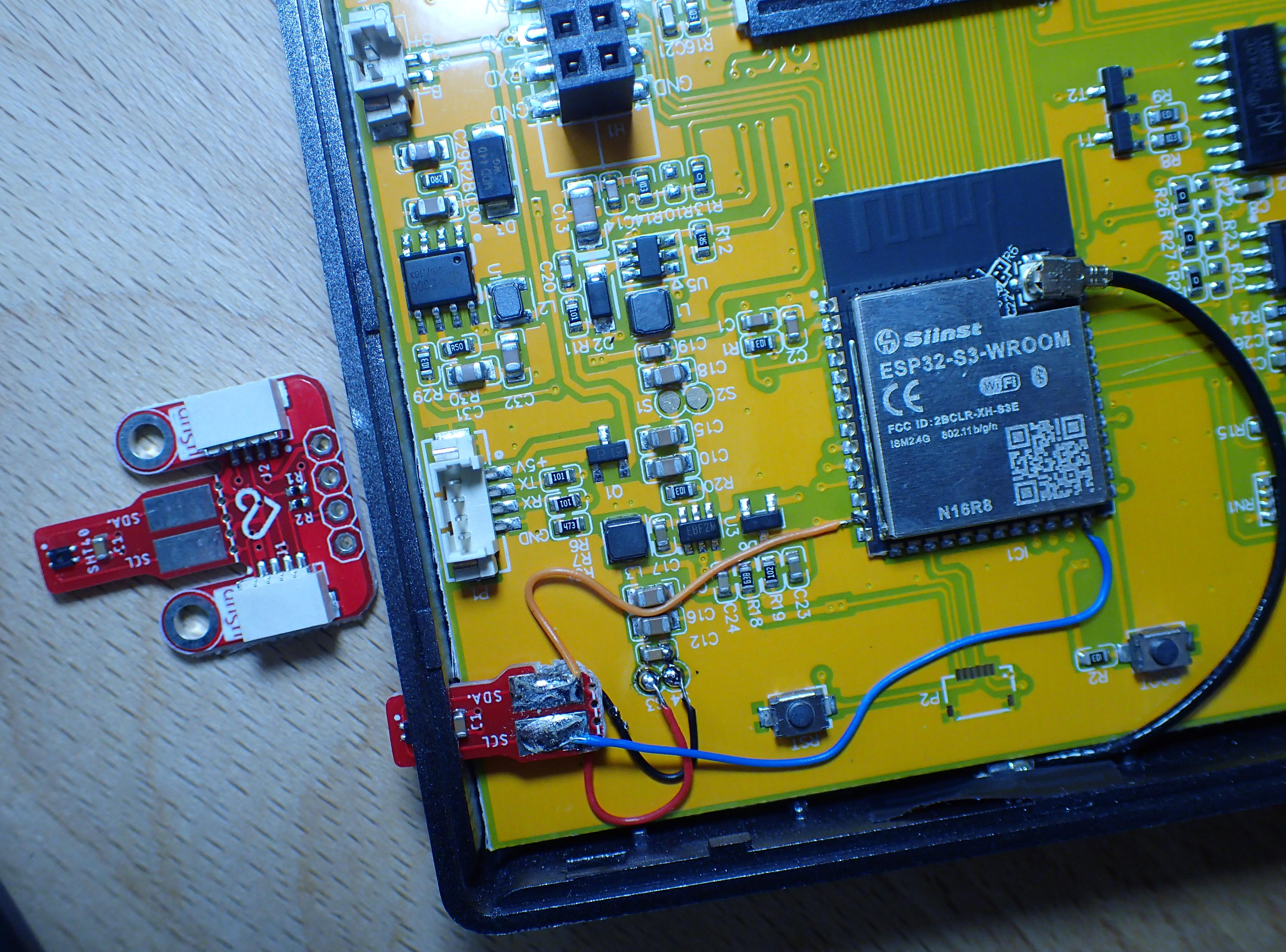
Wiring
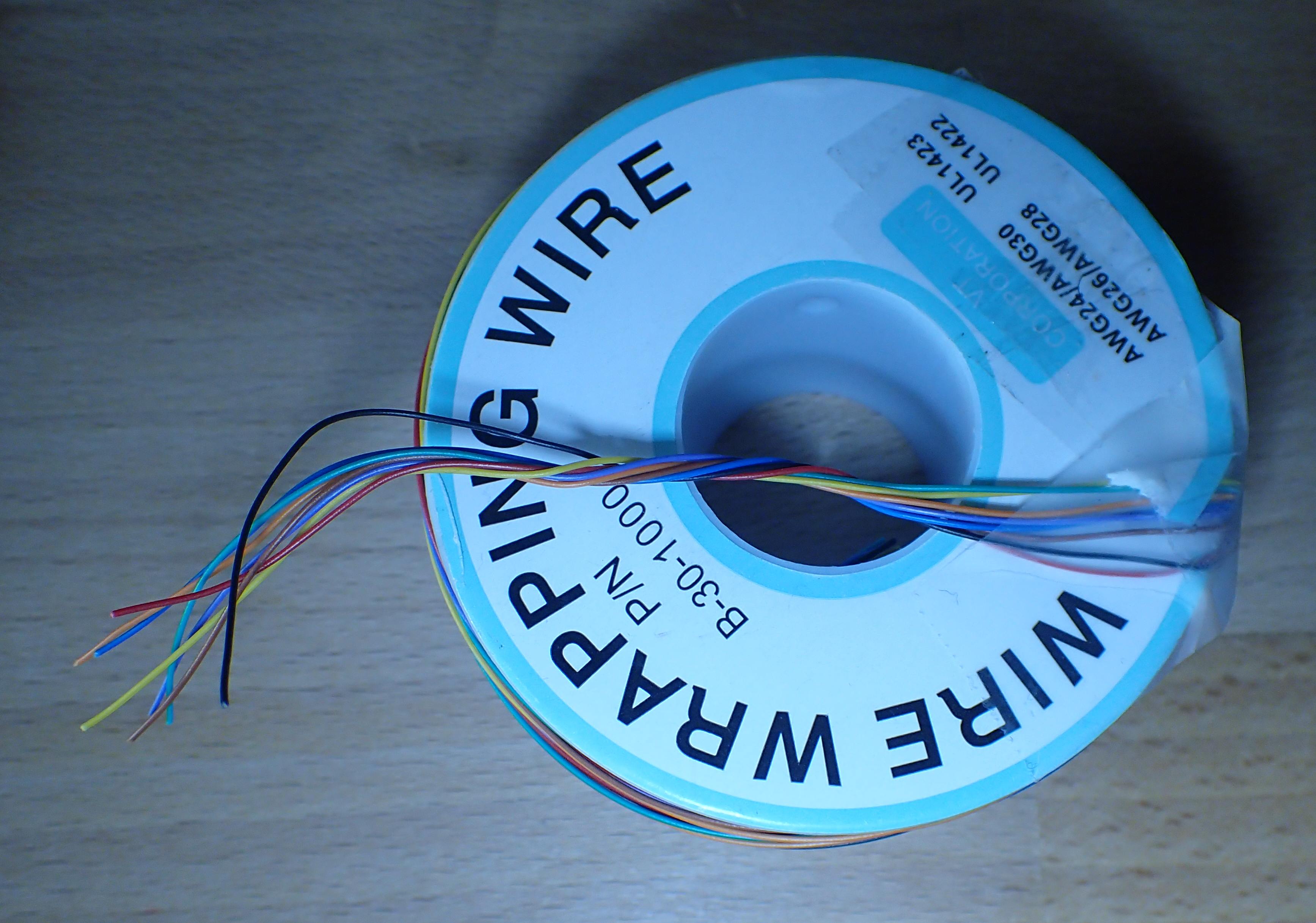
For such jobs, it is best to use wire-wrap wire: it is very fine and has a solid core.
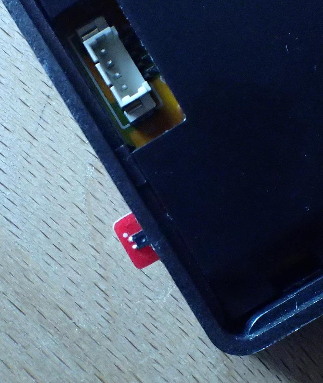
Mechanical
Drilling an extra hole in the plastic case allows easy fixation of the sensor. This way, the sensor measures the outside temperature.
Self-heating via the wires and radiation
The problem
My first attempt of connecting a SHT40 gave a temperature of 28°C in a room that was 21°C. This is definitely not acceptable.
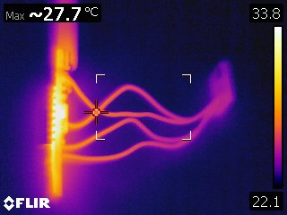
Investigation learned that the whole CPU module and the display backlighting get hot, and consequently the temperature sensor PCB got hotter then the environment. There are some interesting thermal imaging camera pictures, showing this effect at: https://github.com/esphome/issues/issues/2887#issuecomment-1261366222.
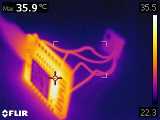
The picture shows a sensor PCB circa 5cm away from a CPU board. The sensor only consumes very little energy, so it should be almost at environmental temperature. The picture show that the CPU is the hottest, and the sensor board is clearly also hotter than the environment. Interesting is, that the wires to the sensor board are hot, too. This hints to thermal flow through the wires to the sensor board. Also, the air around the module gets heated up, since it shows brighter than the background air.
So, we have multiple effects heating the sensor:
- through direct radiation
- heath transmission through the wires
- air flow
Working on the heat production
The person reporting the problem could solve it sufficiently by “changed my program in the sense that the module isn’t alive all the time reporting the temperature every 60 seconds, but instead uses the deep sleep to wake up every 5 minutes and make one measurement, thus not heating up that much”.
I tried reducing the display brightness from 100% to 30% (which is very dim), which resulted in 26.4°C instead of 28.0°C, which proves the importance of the backlighting heat. The display is usable with a dimming of 40% - but then it hums a bit.
Working on the radiation
Furthermore, I made the temperature sensor stick out of the display case even more than on the above pictures. A few millimeter lead to a temperature decrease from 26.4°C to 24.9°C.
Working on the transmission
The transmission through the wires can be reduced by making the wires thinner, longer and less heat conducting.
I already used very fine wire-wrap wire to connect the sensor module: AWG30 = 0.25mm diameter = 0.051mm² cross-section.
I should experiment with longer wires.
Working on the air flow
To improve more, I probably should have put the sensor at the bottom of the module, not at the top left hand side.
The end result
In the end, I cut a small plastic pipe and glued it to the side of the module. So, now the wires are much longer, and the temperature sensor is more at the bottom of the module.


Tasmota software
The command “I2CDevices” lists the supported device identifiers. One of these is the 15, which stands for the SHT3x and SHT4x series of I²C temperature sensors.
Tasmota recognizes the sensor automatically. Other sensors would work also, e.g. the Si7021 is device 9.