RF Gateway
The project I am going to build
The last few weeks, I tried to build the project described here:
https://github.com/cpainchaud/RFLink32
Inspiring Links
https://www.domoticz.com/wiki/Integrations_and_Protocols#315_and_433_MHz
https://www.domoticz.com/wiki/RFLink
https://michiel.vanderwulp.be/domotica/Modules/RF-433Mhz-transmitter-receiver/
This is the project that the Domoticz hardware “RFLink Gateway MQTT” is based on: https://github.com/pagocs/esp32-rflinkmqttgateway
Used modules
https://michiel.vanderwulp.be/domotica/Modules/ESP32-and-Shield/
https://michiel.vanderwulp.be/domotica/Modules/CC1101-433MHz/
Maybe later: https://michiel.vanderwulp.be/domotica/Modules/OLED-Display-SSD1306/
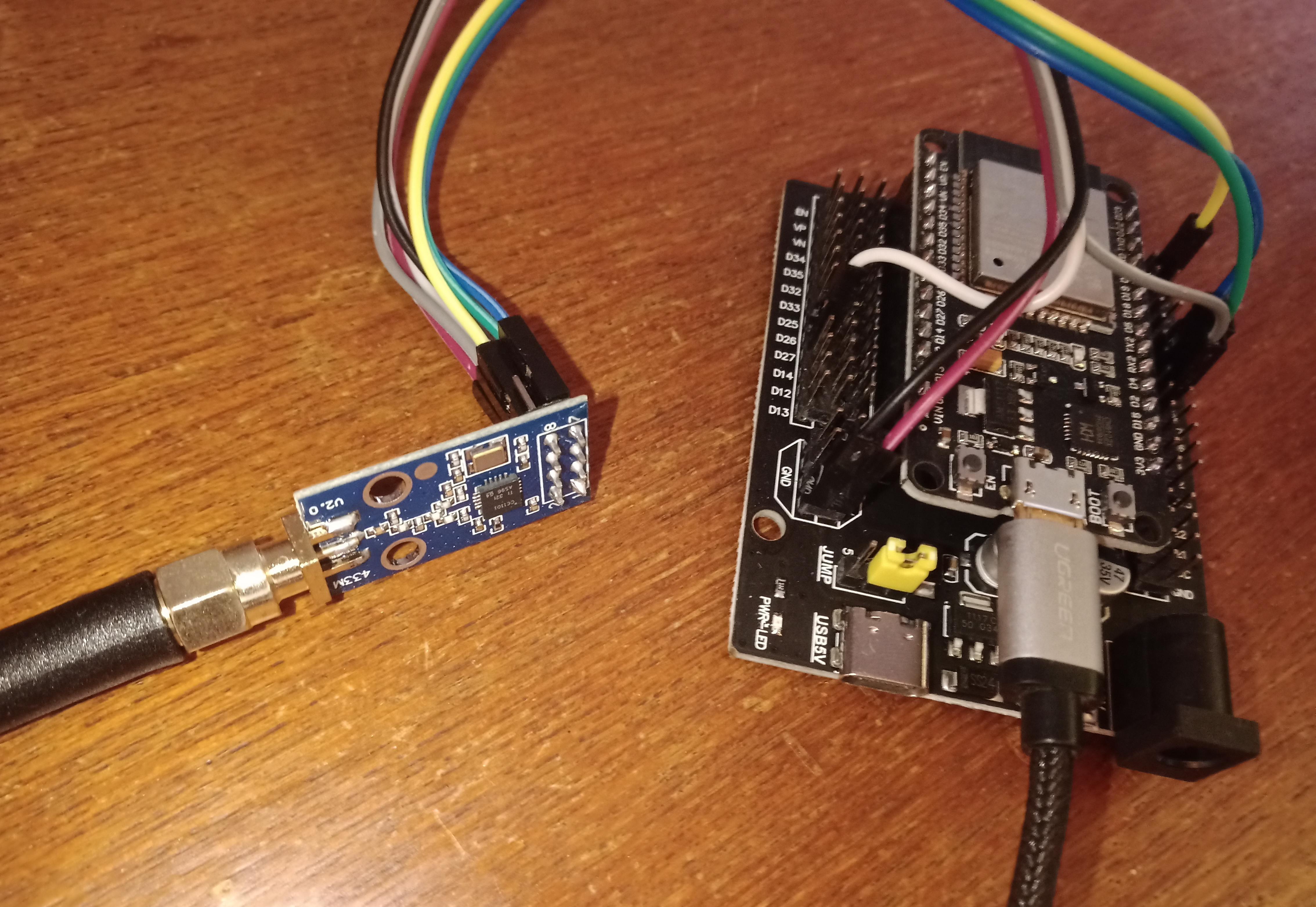
Hardware connections
| Name | ESP32 | CC1101 |
|---|---|---|
| 3v3 | VCC | |
| GND | GND | |
| 18 | SCK | |
| 19 | MISO | |
| 23 | MOSI | |
| pins::RX_RESET | 4¹ | not connected |
| pins::RX_CS | 5¹ | CSN |
| pins::RX_DATA pins::TX_DATA | 26¹ | GDO0 |
¹ These must be configured in the web portal, values suggested here are proven to work reliably.
RFLink install on generic ESP32
I have the Github CLI command gh installed on my system, so that is what I use:
michiel@Delphinus:~/development/github> gh repo clone cpainchaud/RFLink32

michiel@Delphinus:~/development/github> cd RFLink32
I have Platformio Core installed on my system, so that is what I use:
michiel@Delphinus:~/development/github/RFLink32> get_pio
In .bashrc, I have an alias defined as follows: alias get_pio='source ~/.platformio/penv/bin/activate'.
(penv) michiel@Delphinus:~/development/github/RFLink32> pio run

(penv) michiel@Delphinus:~/development/github/RFLink32> pio run -e genericESP32  -t upload

(penv) michiel@Delphinus:~/development/github/RFLink32> pio run -e genericESP32  -t monitor
The serial commands you can give in the monitor/terminal are specified here:.
This RFLink command sets the Wifi credentials - using my mobile phone did not work - fill in the password here!:
10;config;set;{"wifi":{"client_enabled":true,"client_dhcp_enabled":true,"client_ssid":"FRITZ!Box 7530 AA","client_password":"..........."}}
Look for the following line when starting up: WiFi Client has received a new IP: 10.0.3.122.
Next, browse to http://10.0.3.122/ and log in with the default login details: name = rflink32 / password = 433mhz
Hardware malfunction for CC1101 - defect #103
On the serial connection (pio run -e genericESP32 -t monitor) we see continuously:
Now trying to initialize hardware 'CC1101'
Initialized CC1101(freq=433.92Mhz,br=9.600kbps,rxbw=250.0khz)=-104
CC1101 SetOOK(true)=0
CC1101 setPromiscuousMode(true)=0
CC1101 disableSyncWordFiltering(true)=0
Hardware failed to initialize, we will retry later!
Follow instructions here to solve this: https://github.com/cpainchaud/RFLink32/issues/103.
Change ../RFLink32/RFLink/1_Radio.cpp
to have default_rxBandwidth = 203000;
instead of default_rxBandwidth = 250000;.
Then do another pio run -e genericESP32 -t upload - no worry, this retains the configuration.
Startup blah
This text appears after startup of the module on the serial console after the command pio run -e genericESP32 -t monitor:
rst:0x1 (POWERON_RESET),boot:0x13 (SPI_FAST_FLASH_BOOT)
configsip: 0, SPIWP:0xee
clk_drv:0x00,q_drv:0x00,d_drv:0x00,cs0_drv:0x00,hd_drv:0x00,wp_drv:0x00
mode:DIO, clock div:2
load:0x3fff0030,len:1184
load:0x40078000,len:13192
load:0x40080400,len:3028
entry 0x400805e4
E (524) esp_core_dump_flash: No core d.f.p partition found!
E (524) esp_core_dump_flash: No core dump partition found!

Arduino IDE Version :   10812
ESP SDK version:        v4.4.4
Sketch File :           RFLink/RFLink.cpp
Compiled on :           Aug  3 2024 at 16:57:57
20;00;RFLink_ESP;VER=5.1;BUILD=unknown;
Loading persistent filesystem... OK. File system usage: 12/320KB.
Now opening JSON config file '/config.json'
JSON file mem usage: 1800 / 4096
Now dumping JSON file content:
{"wifi":{"client_enabled":true,"client_dhcp_enabled":true,"client_ssid":"FRITZ!Box 7530 AA","client_password":".................","client_ip":"192.168.0.200","client_mask":"255.255.255.0","client_gateway":"192.168.0.1","client_dns":"192.168.0.1","client_hostname":"RFLink32","ap_enabled":true,"ap_ssid":"RFLink-AP","ap_password":"","ap_ip":"192.168.4.1","ap_network":"192.168.4.0","ap_mask":"255.255.255.0"},"mqtt":{"enabled":true,"server":"mqtt","port":1883,"id":"RFLink32","user":"","password":"","topic_in":"/ESP00/cmd","topic_out":"/ESP00/msg","lwt_enabled":true,"topic_lwt":"/ESP00/lwt","ssl_enabled":false,"ssl_insecure":true,"ca_cert":""},"serial2net":{"enabled":false,"port":1900},"portal":{"enabled":true,"auth_enabled":true,"auth_user":"rflink32","auth_password":"433mhz"},"signal":{"async_mode_enabled":false,"sample_rate":1,"min_raw_pulses":24,"seek_timeout":25,"min_preamble":100,"min_pulse_len":90,"signal_end_timeout":5000,"signal_repeat_time":250,"scan_high_time":50},"radio":{"hardware":"CC1101","rx_data":26,"rx_vcc":-1,"rx_nmos":-1,"rx_pmos":-1,"rx_gnd":-1,"rx_na":-1,"rx_reset":-1,"rx_cs":5,"tx_data":26,"tx_vcc":-1,"tx_nmos":-1,"tx_pmos":-1,"tx_gnd":-1}}
Switching from Radio hardware 'generic' to 'CC1101'
Initialized CC1101(freq=433.92Mhz,br=9.600kbps,rxbw=203.0khz)=0
CC1101 SetOOK(true)=0
CC1101 setPromiscuousMode(true)=0
CC1101 disableSyncWordFiltering(true)=0
Hardware initialization was successful!
Applied slicer 'Legacy'
Signal parameters have changed.
* WIFI AP starting with SSID 'RFLink-AP' and band=11... OK
Trying to connect WIFI SSID FRITZ!Box 7530 AA. A status will be given whenever it occurs.
E (1326) gpio: gpio_isr_handler_remove(480): GPIO isr service is not installed, call gpio_install_isr_service() first
E (1327) gpio: gpio_wakeup_disable(579): GPIO number error
E (1331) gpio: gpio_set_intr_type(147): GPIO number error
Radio pin RF_RX_DATA :  26
Radio pin RF_RX_CS :    5
Radio pin RF_TX_DATA :  26
Starting WebServer... OK
Connected to AP SSID:FRITZ!Box 7530 AA  BSSID: DC:39:6F:F3:0D:7D  Channel: 6  Auth mode: 3
WiFi Client has received a new IP: 10.0.3.122
MQTT parameters have changed, first disconnecting...
MQTT parameters have changed, now applying...
Trying to connect to MQTT Server 'mqtt' ... Established
MQTT ID :               RFLink32
MQTT Username :
NTP synchronized: 2024-08-04 13:21:07
MQTT settings
LWT : Last Will and Testament
What is the MQTT topic that the module should use? I did not find any prescription for this. There is a topic given in https://github.com/domoticz/domoticz/blob/development/hardware/RFLinkMQTT.cpp. So, that is what I used:
| Subject | Default Topic | Change to topic |
|---|---|---|
| Topic In | /ESP00/cmd | rflink/out |
| Topic Out | /ESP00/msg | rflink/in |
| Topic LWT | /ESP00/lwt | rflink/lwt |
Discover signals
After starting the RFLink board, place it in debug mode by issuing this command on the serial port:
10;RFDEBUG=ON;
This will ensure that anytime a set of RF pulses is received and not recognized by a plugin that it will be output.
The syntax for RFLink is here: https://www.rflink.nl/protref.php.
Listen to MQTT
Execute the following in a terminal window on a PC:
michiel@Delphinus:~> mosquitto_sub -h mqtt -t "rflink/#" -v
Pressing the ‘+’ on the kichen fan remote gives:
rflink/out 20;11;X10;ID=0aaa;SWITCH=01;CMD=ON;
So, this proves that the module receives signals.
The kitchen fan
Received on MQTT topic “rflink/out”:
| Button | MQTT message | Description/Remarks |
|---|---|---|
| + | 20;21;X10;ID=0aaa;SWITCH=01;CMD=ON; | From very close by |
| + | 20;08;CAME-TOP432;ID=0aaa;SWITCH=01;CMD=ON; | From 1m distance |
| - | 20;22;X10;ID=0aa9;SWITCH=01;CMD=ON; | From very close by |
| - | 20;19;CAME-TOP432;ID=0aa9;SWITCH=01;CMD=ON; | From 1m distance |
| Light | 20;08;CAME-TOP432;ID=0a2e;SWITCH=01;CMD=ON; | From 1m distance |
| Novy | 20;24;X10;ID=0aab;SWITCH=01;CMD=ON; | From 1m distance |
| On/Off | 20;07;CAME-TOP432;ID=0a2c;SWITCH=01;CMD=ON; | From 1m distance |
The second number is a sequence number, should be ignored here.
Sending RF via MQTT
The following should command the RFLink module to transmit the ‘+’ RF command to the kitchen fan:
michiel@Delphinus:~> mosquitto_pub -h mqtt -t "rflink/in" -m '10;CAME-TOP432;0aaa;01;ON;'
michiel@Delphinus:~> mosquitto_pub -h mqtt -t "rflink/in" -m '10;X10;0aaa;01;ON;'
On mosquitto_sub, the RFLink module responds:
rflink/in 10;CAME-TOP432;0aaa;01;ON;
rflink/out 20;02;OK;

rflink/in 10;X10;0aaa;01;ON;
rflink/out 20;03;OK;
But there is no response from the fan …
I won’t progress here unless I start looking at the incoming and outgoing signals with an oscilloscope.
How to use domoticz hardware
https://github.com/pagocs/esp32-rflinkmqttgateway
Apparently, a device is created in the RFLink hardware. Which I do not understand - this not what we want here.
- In Domoticz, in the hardware list, add “RFLink Gateway MQTT” device.
- Press the button “Create RFLink Devices”.
- Enter a name, e.g. “Keuken Fan Plus”. Press OK.
- Then press the RF remote button. Apparently, this is the way to learn a device in Domoticz.
- Now, I see in MQTT:
;flink/out 11;Keuken Fan Plus
The 11 means creation of devices … see https://www.rflink.nl/protref.php.
But no device appears in Domoticz … how does this work?
Project status
So, this is how far I got with this project.
I received some signals from the kitchen fan remote control, but nothing from the curtains remote control. I did not succeed to send any signal to any device - at least, the device did not react.
The next step is to look at the signals with an oscilloscope.
Maybe the CC1101 is not a good choice? Should I try the alternative SRX882 / STX882 module that I received?