Install and configure Tasmota
The goal of this page is to install and configure Tasmota on an ESP32-C3 module. When done, we add hardware to measure and display the CO2 level in the room.
The module is a esp32-c3 SuperMini.
For installation, we use esptool from Espressif.
Install esptool
See Espressif esptool.
After install, verify:
michiel@Delphinus:~> which esptool.py
/home/michiel/.local/bin/esptool.py
michiel@Delphinus:~>
Connect the esp32-c3 SuperMini and erase
Connect a data USB-C cable from your PC to the ESP32-C3.
As described at Tasmota - Getting started, we erase the flash first. No need to specify the serial port to use - we are using Linux. No need to put the device in programming mode - modern devices do that automatically.
michiel@Delphinus:~> esptool.py erase_flash
esptool.py v3.3.3
Found 2 serial ports
Serial port /dev/ttyS4
Connecting......................................
/dev/ttyS4 failed to connect: Failed to connect to Espressif device: No serial data received.
For troubleshooting steps visit: https://docs.espressif.com/projects/esptool/en/latest/troubleshooting.html
Serial port /dev/ttyACM0
Connecting...
Detecting chip type... ESP32-C3
Chip is ESP32-C3 (revision v0.4)
Features: Wi-Fi
Crystal is 40MHz
MAC: 64:e8:33:84:1e:dc
Uploading stub...
Running stub...
Stub running...
Erasing flash (this may take a while)...
Chip erase completed successfully in 18.9s
Hard resetting via RTS pin...
michiel@Delphinus:~>
You need to reset the device now by pressing on its reset button before flashing it in the next step!
Get the correct Tasmota binary
Download the file from https://github.com/tasmota/install/blob/firmware/firmware/unofficial/tasmota32c3-lvgl.bin
But, initially we need a factory binary for inital flashing using esptool, see http://ota.tasmota.com/tasmota32/release/ We can use tasmota32c3.factory.bin or the file from here: https://github.com/tasmota/install/blob/firmware/firmware/unofficial/tasmota32c3-lvgl.factory.bin
These are the two we will use:
michiel@Delphinus:~> cd Downloads/
michiel@Delphinus:~/Downloads> ls -lrt
... # many more files
-rw-r--r-- 1 michiel users    2746464 27 dec 10:53 tasmota32c3-lvgl.bin
-rw-r--r-- 1 michiel users    3665120 27 dec 15:36 tasmota32c3-lvgl.factory.bin
michiel@Delphinus:~/Downloads>
Flashing the Tasmota firmware
We use the following command: esptool.py write_flash 0x0 tasmota32c3-lvgl.factory.bin
michiel@Delphinus:~/Downloads> esptool.py write_flash 0x0 tasmota32c3-lvgl.factory.bin
esptool.py v3.3.3
Found 2 serial ports
Serial port /dev/ttyS4
Connecting......................................
/dev/ttyS4 failed to connect: Failed to connect to Espressif device: No serial data received.
For troubleshooting steps visit: https://docs.espressif.com/projects/esptool/en/latest/troubleshooting.html
Serial port /dev/ttyACM0
Connecting....
Detecting chip type... ESP32-C3
Chip is ESP32-C3 (revision v0.4)
Features: Wi-Fi
Crystal is 40MHz
MAC: 64:e8:33:84:1e:dc
Uploading stub...
Running stub...
Stub running...
Configuring flash size...
Flash will be erased from 0x00000000 to 0x0037efff...
Compressed 3665120 bytes to 2183590...
Wrote 3665120 bytes (2183590 compressed) at 0x00000000 in 50.2 seconds (effective 583.8 kbit/s)...
Hash of data verified.

Leaving...
Hard resetting via RTS pin...
michiel@Delphinus:~/Downloads>
Use Python miniterm as serial monitor
We can use a simple terminal emulater to show the serial output from the module and to send it some commands.
On my OpenSuse Leap system, I installed miniterm, which is part of PySerial:
michiel@Delphinus:~> sudo zypper in python3-pyserial
Start miniterm without parameters, and it will ask you for the port:
michiel@Delphinus:~/Downloads> which miniterm
/usr/bin/miniterm
michiel@Delphinus:~/Downloads> miniterm

--- Available ports:
---  1: /dev/ttyACM1         'USB JTAG/serial debug unit'
---  2: /dev/ttyS4           'n/a'
--- Enter port index or full name: 1
--- Miniterm on /dev/ttyACM1  9600,8,N,1 ---
--- Quit: Ctrl+] | Menu: Ctrl+T | Help: Ctrl+T followed by Ctrl+H ---
6.777 QPC: Reset
00:00:32.269 CMD: QPC: Count 1
00:00:32.273 RSL: RESULT = {"Command":"Unknown","Input":"QPC : Count 1"}
00:00:32.321 CMD:
On more recent installs of OpenSUSE, miniterm will install under a different name:
michiel@Delphinus:~> which pyserial-miniterm
/home/michiel/.pyenv/shims/pyserial-miniterm
Setting the Wifi credentials via the serial connection
You will have to enter a backlog command in miniterm as follows (and concluding by pressing the enter key):
backlog ssid1 FRITZ!Box 7530 AA; password1 xxxMySecretPasswordxxx
Problem is, that you do not see anything when typing it. So, it is easier to just copy it from elsewhere and paste it in.
Do not worry, if your SSID contains spaces or special characters - mine is “FRITZ!Box 7530 AA” - it works as long as the “;” can be used as a delimiter.
michiel@Delphinus:~/Downloads> miniterm

--- Available ports:
---  1: /dev/ttyACM1         'USB JTAG/serial debug unit'
---  2: /dev/ttyS4           'n/a'
--- Enter port index or full name: 1
--- Miniterm on /dev/ttyACM1  9600,8,N,1 ---
--- Quit: Ctrl+] | Menu: Ctrl+T | Help: Ctrl+T followed by Ctrl+H ---
6.777 QPC: Reset
00:00:32.269 CMD: QPC: Count 1
00:00:32.273 RSL: RESULT = {"Command":"Unknown","Input":"QPC : Count 1"}
00:00:32.321 CMD:

    <-- here you paste the backlog command!

00:00:56.874 CMD:
00:01:00.333 CMD: backlog ssid1 FRITZ!Box 7530 AA; password1 xxxMySecretPasswordxxx
00:01:00.380 RSL: RESULT = {"SSId1":"FRITZ!Box 7530 AA"}
00:01:00.585 RSL: RESULT = {"Password1":"xxxMySecretPasswordxxx"}
00:01:02.229 APP: Restarting
ESP-ROM:esp32c3-api1-20210207
Build:Feb  7 2021
rst:0xc (RTC_SW_CPU_RST),boot:0xf (SPI_FAST_FLASH_BOOT)
Saved PC:0x40382286
SPIWP:0xee
mode:DIO, clock div:1
load:0x3fcd5820,len:0x98
load:0x403cc710,len:0x870
load:0x403ce710,len:0x21bc
entry 0x403cc710

00:00:00.001 CMD: Using USB CDC
00:00:00.001 HDW: ESP32-C3 v0.4
00:00:00.012 UFS: FlashFS mounted with 308 kB free
00:00:00.023 CFG: Loaded from File, Count 10
00:00:00.026 SER: Set to 8N1 115200 bit/s
00:00:00.026 SER: HWCDC supports 115200 bit/s only
00:00:00.031 QPC: Count 1
00:00:00.071 BRY: Berry initialized, RAM used 5697 bytes
00:00:00.084 Project tasmota - Tasmota Version 14.4.1.1(7f8f614-lvgl-haspmota)-3_1_0(2024-12-27T13:56:58)
00:00:01.002 WIF: Connecting to AP1 FRITZ!Box 7530 AA in mode HT40 as tasmota-841EDC-7900...
00:00:03.318 WIF: Connected
00:00:03.623 HTP: Web server active on tasmota-841EDC-7900 with IP address 10.0.3.224
16:04:03.682 RSL: INFO1 = {"Info1":{"Module":"ESP32C3","Version":"14.4.1.1(7f8f614-lvgl-haspmota)","FallbackTopic":"cmnd/DVES_841EDC_fb/","GroupTopic":"cmnd/tasmotas/"}}
16:04:03.685 RSL: INFO2 = {"Info2":{"WebServerMode":"Admin","Hostname":"tasmota-841EDC-7900","IPAddress":"10.0.3.224","IP6Global":"","IP6Local":"fe80::66e8:33ff:fe84:1edc%st1"}}
16:04:03.687 RSL: INFO3 = {"Info3":{"RestartReason":"Software reset CPU","BootCount":6}}
16:04:06.005 QPC: Reset
16:04:07.964 RSL: STATE = {"Time":"2024-12-27T16:04:07","Uptime":"0T00:00:09","UptimeSec":9,"Heap":169,"SleepMode":"Dynamic","Sleep":50,"LoadAvg":19,"MqttCount":0,"Berry":{"HeapUsed":5,"Objects":55},"Wifi":{"AP":1,"SSId":"FRITZ!Box 7530 AA","BSSId":"DC:39:6F:F3:0D:7D","Channel":1,"Mode":"HT40","RSSI":34,"Signal":-83,"LinkCount":1,"Downtime":"0T00:00:04"}}
This worked!
We can now use Tasmota’s webserver, as described above:
Web server active on tasmota-841EDC-7900 with IP address 10.0.3.224
Use the Tasmota web server
The Tasmota software includes a webserver that you can access on your PC. This is a much easier way of monitoring and configuring the module. Here you can flash new firmware and configure the hardware you will connect.
In the webbrowser on your PC, go to the IP address mentioned above. You should see the following menu:

Flash a new firmware
From the web server menu, select “Firmware upgrade”, click the “Browse” button, and choose the “tasmota32c3-lvgl.bin” we downloaded before.

Then press the “Start upgrade” button.
Tasmota will now download the bin file first, and then restart with the new firmware. The hexadecimal code at the bottom of the screen is now different:
Adding hardware
The parts
- The CO2 sensor SCD41.
- The CPU module ESP32-C3-SuperMini, plus extension board.
- A TM1637 red LED 7-segment display module.
PDF datasheet of the TM1637.
Wiring of the ESP32-C3 and the CO2 sensor

| Module | pin | pin | Module |
|---|---|---|---|
| SCD41 | GND | GND | ESP32-C3-SuperMini |
| SCD41 | VDD | 3V3 | ESP32-C3-SuperMini |
| SCD41 | SCL | 9 | ESP32-C3-SuperMini |
| SCD41 | SDA | 8 | ESP32-C3-SuperMini |
Adding a RGB LED

| Module | pin | pin | Module |
|---|---|---|---|
| RGB LED | Red wire | 2 | ESP32-C3-SuperMini |
| RGB LED | Green wire | 3 | ESP32-C3-SuperMini |
| RGB LED | Yellow wire | 4 | ESP32-C3-SuperMini |
| RGB LED | Common Anode - White wire | 3V3 | ESP32-C3-SuperMini |
Connect the TM1637 display module

According to the description at https://tasmota.github.io/docs/TM163x/, we can use any GPIO pin for the DIO and CLK pins of the TM1637.
| Module | pin | pin | Module |
|---|---|---|---|
| TM1637 | GND | GND | ESP32-C3-SuperMini |
| TM1637 | 5V | 5V | ESP32-C3-SuperMini |
| TM1637 | DIO | 0 | ESP32-C3-SuperMini |
| TM1637 | CLK | 1 | ESP32-C3-SuperMini |
Templates
See https://templates.blakadder.com/SuperMini-ESP32-C3.html
Use this as template:
{"NAME":"SuperMini ESP32-C3","GPIO":[7136,7104,416,417,418,0,1,1,640,608,1,0,0,0,0,0,0,0,1,1,1,0],"FLAG":0,"BASE":1}
Set the name to CO2SensorTM1637.
Set the friendly1 name to CO2 Sensor TM1637.
Save and restart the module.
Compile own firmware
Since the TM1637 is not included in any pre-build software, we can not choose the TM1637 DIO and TM1637 CLK for the GPIO 0 and 1.
This means we have to build and configure our own Tasmota firmware.
Once the new firmware is flashed, we can continue configuering Tasmota.
Configure the template
Go to the configuration of the template and set the foillowing values:

This results in:

Configure the module
Set the hostname
12:03:05.287 CMD: hostname CO2SensorTM1637
12:03:05.291 RSL: RESULT = {"Hostname":"CO2SensorTM1637"}
Set the SCD41 Altitude
See description at https://tasmota.github.io/docs/SCD4x/#first-installation
I live at around 12m altitude, so these commands will configure the sensor:
SCD40Stop
SCD40Alt 12
SCD40Toff 400
SCD40pers
Enter these at the “Console” screen under the “Tools” menu:
18:22:58.399 CMD: SCD40Stop
18:22:58.405 RSL: RESULT = {"SCD40Stop":0}
18:23:01.663 CMD: SCD40Alt 12
18:23:01.669 RSL: RESULT = {"SCD40Alt":0}
18:23:04.520 CMD: SCD40Toff 400
18:23:04.526 RSL: RESULT = {"SCD40Toff":0}
18:23:15.754 CMD: SCD40pers
18:23:15.760 RSL: RESULT = {"SCD40Pers":0}
The “Result = 0” means that it worked.
Restart the module to see the periodic measurements again!
This configuration is persisted in the SCD41 module, so it has to be done only once per SCD41 module.
Set the SCD41 to low power mode
Since I would like to be able to use this module with a battery, I would like to use the low power mode of the SCD41.
See https://tasmota.github.io/docs/SCD4x/#commands
SCD40Stop
SCD40StLp
Enter these at the “Console” screen under the “Tools” menu:
18:27:56.385 CMD: SCD40Stop
18:27:56.391 RSL: RESULT = {"SCD40Stop":0}
18:28:00.348 CMD: SCD40StLp
18:28:00.354 RSL: RESULT = {"SCD40StLP":0}
Restart the module to see the periodic measurements again!
Setting the teleperiod
The console in the Tasmota web-UI shows measurements from sensors as soon as they arrive. Independently, at a certain interval called the “teleperiod”, a Tasmota device reports its status and measured values to other devices or platforms (often via MQTT).
By default, this interval is 300 seconds (5 minutes). You can adjust this interval, but it cannot be less than 10 seconds. For me, 300 seconds is a bit long, so we change to 30s:
20:08:19.732 CMD: teleperiod 30
20:08:19.737 MQT: stat/tasmota_A177FC/RESULT = {"TelePeriod":30}
In the console, you will now see, every 30s, the Tasmota report its status and sensor values.
Update the LED and display with the measured value
Install the autoexec.be
Now, we are lacking two functionalities:
- At every update of the measured CO2 value, we need to display it on the 7-segment display.
- At every update of the measured CO2 value, we need to calculate the color-LED color.
We will implement this in the programming language Berry, by uploading a file named autoexec.be here to the Tasmota filesystem.
Set the LED color according the CO2 level
The LED should depend on the measured CO2 value.
| CO2 value | LED Color | Command |
|---|---|---|
| <400 | off | color1 255,255,255 |
| 400 .. 800 | Green | color1 255,0,0 |
| 800 .. 1200 | Yellow/Orange | color1 0,255,0 |
| >1200 | Red | color1 0,255,255 |
To test the events, we add this to the autoexec.be here:
def co2value(value, trigger, msg)
    print (str(value) .. " - " .. trigger .. " - " .. msg)
end
tasmota.add_rule("SCD40#CarbonDioxide", co2value)
The returned values look like this:
18:30:13.473 465 - SCD40#CarbonDioxide - {'SCD40': {'CarbonDioxide': 465, 'Temperature': 25.7, 'Humidity': 57, 'eCO2': 489, 'DewPoint': 16.5}}
So, we can use the first value as an integer:
def co2value(value)
    if (value < 400)
        tasmota.cmd("color1 255,255,255")
    elif (value < 800)
        tasmota.cmd("color1 255,0,0")
    elif (value < 1200)
        tasmota.cmd("color1 0,255,0")
    else
        tasmota.cmd("color1 0,255,255")
    end
end
tasmota.add_rule("SCD40#CarbonDioxide", co2value)
This last code generates much traffic on the MQTT bus for LED updates. So, we could replace the rule trigger to only trigger every teleperiod:
tasmota.add_rule("Tele#SCD40#CarbonDioxide", co2value)
But that also causes the colour LED update to be delayed - this does not feel good. So, I added some code to check the previous colour, and only adapt the colour if it differs from the last value. See the autoexec.be here file for the complete code.
Update the TM1637 display whenever a new value is measured
If we go to the menu “Tools” and then “Console”, we can enter a command to show a number on the TM1637 display:
21:18:49.766 CMD: DisplayText 5000
21:18:49.775 RSL: RESULT = {"DisplayText":"5000"}
We can use this function to show the measured CO2 value with some Berry code. Add the following to the autoexec.be here:
var oldvalue = 5000
def ud(value)
    if (value != oldvalue)
        tasmota.cmd("DisplayText " .. value)
        oldvalue = value
    end
end
tasmota.add_rule("SCD40#CarbonDioxide", ud)
The DisplayText always aligns its text at the left, and it would be better if it were aligned to the right.
The DisplayNumber command can solve this problem, but is a bit more complicated:
tasmota.cmd("DisplayNumber " + str(value) + ", 0, 0, 4")
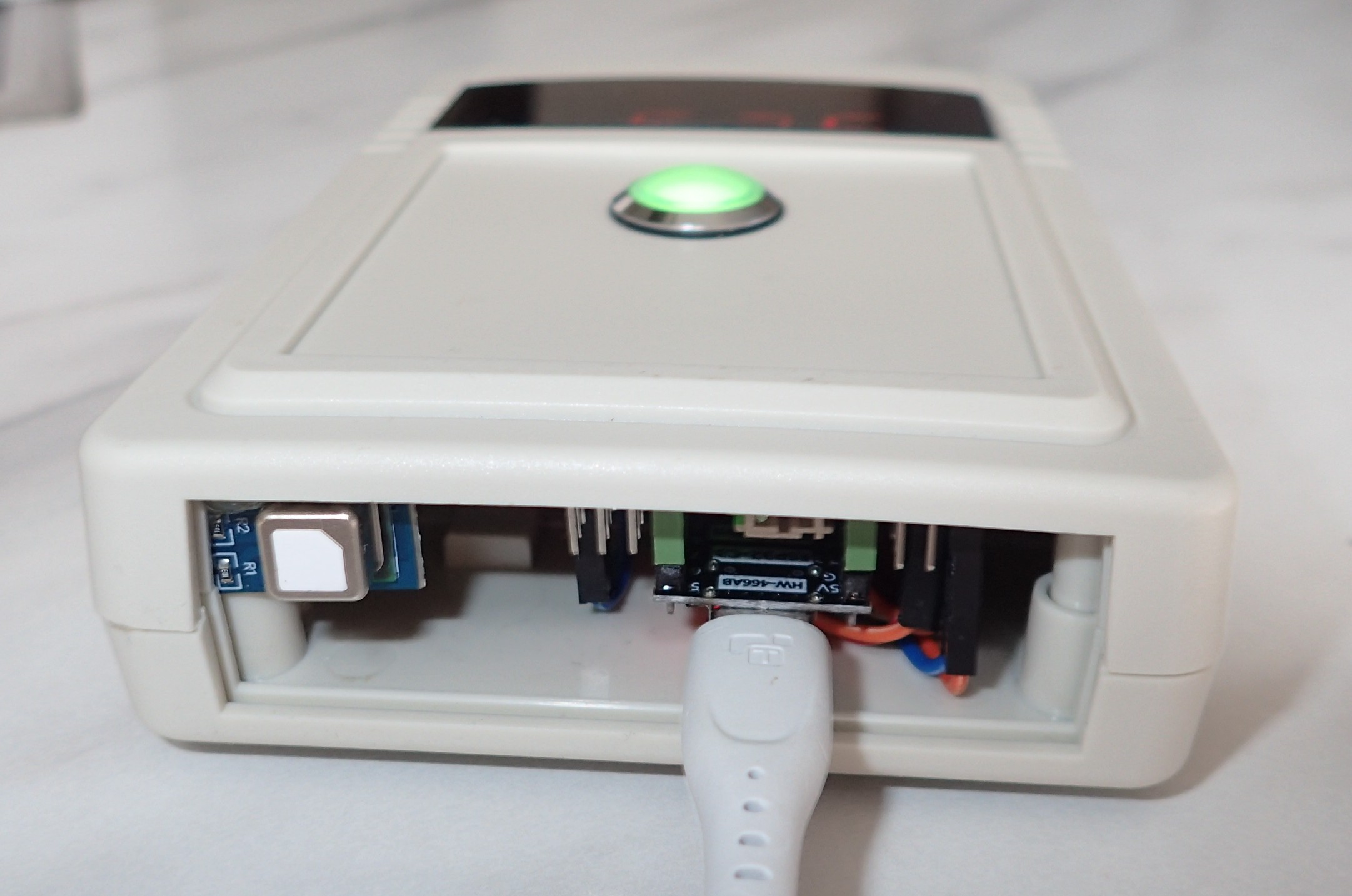
The end result