Project M
Status of the project
This project was executed end may 2026.
Electric boiler and gas-geyser
A geyser (or instantaneous water heater) heats water on demand as it passes through, providing unlimited hot water but no storage. A boiler stores a fixed amount of water in a tank, keeping it hot for instant use.
In our country, almost all geysers are burning natural gas to heat the water, and the boilers are using electricity to warm the water.
Context
I have solar panels without battery, and a watergeyser on gas.
This project aims to add an electric waterboiler which only heats water with excess electricity from the solar panels, and switch automatically between both systems.
Architecture of the system
Installing an extra electric waterboiler is standard work for a hired plumber, and even possible DIY. This involves connecting waterpipes and connecting electricity to the electric boiler heater element. Probably you want to add a (manual) valve-switch so that you can choose between the gas geyser (in the winter) and the electric boiler (in the summer).
It is more complicated to make the system automatic, following following algorithm:
- The valve position depends on the hot-water temperature in the top of the electric boiler.
- The electric boiler heater element only consumes excess electricity (in a system with or without battery).
This involves
- a motorised valve-switch to choose between the both systems,
- an electronic control-unit,
- a temperature sensor in the top of the electric water boiler.
Detailed architecture of the system
The system will consist of the following components.
Component: MQTT broker
One component shall provide a MQTT broker. It will receive data and send it through to subscribers. The main intention here is reducing dependencies: every component only depends on the presence of the MQTT broker, not on the other components.
Component: Mains consumption/production measurement
One component shall measure the actual house electricity consumption or production. The measurements are posted on the MQTT broker.
Component: Waterboiler heater element
This project aims to add an additional electric waterboiler, and run the electric waterboiler only on excess electricity from the solar panels.
One component shall control the electric current through the waterboiler heater element. Since this heater element is a resistive load, it can be proportionally controlled. This component will be based on a Tasmota ESP32 module, which outputs a PWM signal, which then is converted in a 0..5V voltage by a PWM to Voltage converter with GP8101, which then controls a Voltage controlled input SCR regulator module, which regulates the current through the waterboiler resistor. This is a proven and reliable system (see project solarheater).
Component: Three-way valve
If there is no hot water left in the electric waterboiler, and hot water is requested, then the gas-boiler should take over. This is possible by an electric three-way valve fitted in the hot-water pipe. We use a brass motorized ball valve with 3-Wire electric control on AC 230V with manual switch. The manual switch allows overruling the system when the electricity is down.
Component: Temperature sensor
To know which source of hot water to use, we need to measure if the water in the electric boiler is warm enough. To this end, we need to mount a DS18B20 temperature sensor inside it. This is not easy: we have to open this boiler, drill a hole somewhere to enter the temperature sensor, and close it tight enough to withstand the water pressure.
Component: Control system
Last but no least, control component shall contain the smart software to check the measurements and settings, contain the algorithms, and steer the waterboiler. This component shall also allow the enduser to overrule the algorithm: switch the waterboiler permanently on or off, or on automatic position.
This can be done by an ESP32c3 with Tasmota and using the Berry language for the automation software.
Optionally, we could add a few LEDs, or a display, to show what is going on. Maybe with buttons, or even a touch interface.
Hence, the control component is responsible for all these functions:
- listening to the mains electricity measurements,
- regulate the current through the heater element depending on the mains electricity measurements,
- measuring the water temperature inside in the electric boiler,
- switching the bi-stable three-way valve depending on the measured boiler water temperature,
- optionally: displaying status on LEDs or a display and react on button or touch presses.
UML Component diagram
Hardware - the parts
CPU: ESP32-C3 Supermini
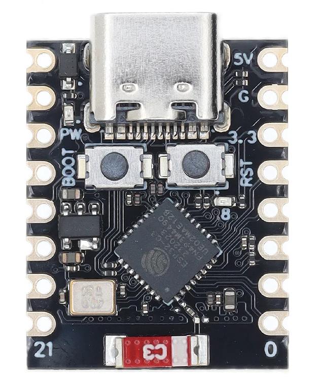
This module is cheap and easy to get. It has enough I/O pins for this purpose. It supports Tasmota and Berry. See ESP32-C3-SuperMini. This module can communicate with the outside world via its Wifi, and controls all other modules.
PWM to 5V DC converter

This module converts the PWM output signal from a typical 3.3V CPU into a DC voltage from 0..5V. See PWMtoVoltageConverter.
Voltage controlled input SCR module

This module can proportionally control the current through a 230VAC load, depending on its 0V .. 5V input. See VoltageControlledInputSCRModule.
Dual relay module

This module is controlled by the CPU, and switches the bi-stable valve motor. See RelayModule2Channel.
Power relay module

The power through the waterboiler heating element is regulated by a SSR, and additionally switched on or off by a power relay module. This will eliminate leaking current and high tension when the heating element is supposed to be off.
The 12V relay module has a jumper to select between active high or active low - we use this module with the jumper on active high, since this allows us to switch the relay with an ESP CPU that runs on a voltage of only 3.3V. Measurements reveal that the relay attracts (click) at 2.4V, and then falls back off (clack) at 1.7V.
Power supply 230V AC to 12V DC

This is a small 100V-240V to DC 12V 1A switching power supply module with overvoltage, overcurrent and short circuit protections. It is cheap and well protected.
Power supply 12V to 5V

This small board contains a DC-DC convertor to create 5VDC from the 12V input. It is pin-out compatible with the famous legacy 7805 regulator.
2 bi-color LEDs for in the front panel

A red and a green LED are assembled in a nice metal housing to be mounted in a front panel. Current limiting resistors (for 3..5V) are included in the housing.
These will indicate the status of the system. Green means “the valve is in this position” and red means “the valve motor is running”.
When both the red and the green LED are on, the resulting color is yellow-green-ish.
Bi-stable valve DN20

This is a ball-valve, operated by a 230VAC motor. The motor inside the valve has 3 wires. To turn the valve, it needs 230VAC on one wire for about 15s. The motor runs during this time, and then automatically breaks the current. To turn the valve back, the motor needs 230VAC on the other wire. Bad things may happen if you put power on both sides at the same time.
See Motorized Ball Valve. We use the 220V AC version here.
Waterboiler with mechanical thermostat and temperature sensor
A standard electrical waterboiler, 150l, 1800W, modified by adding a temperature sensor at the top.
The waterboiler modification
Context
Most of the solutions involving an electric waterboiler require the knowledge of the temperature in the top of the watertank - since that is where the water at the output is drawn from.
Most (cheap) standard boilers have no such temperature sensor, so we need to add one. Here we describe how.
Since this project is intended to save money, we start with a second-hand waterboiler.
The heater element
A standard 150l waterboiler has a resistive heating element that consumes about 1800W. It contains a mechanical thermostat that can be adjusted by turning a knob.
Do not modify this part, it is needed for safe operation! It prevents the water from overheating and boiling.
The anode
The anode is a special metal bar mounted inside the tank to reduce the rusting of the steel wall and the heater element. Normally, they are made of magnesium and need to be replaced after a few years.
The over-pressure protection
Boiling would cause the pressure to increase - each waterboiler also has an overpressure protection system. Also, heating the water makes it expand, which also increases the pressure. In normal use, quite some water drips out of the pressure valve.
The non-return valve (NRV)
Heating the water in the boiler makes it expand, and hence the pressure may increase, so that the water is pushed back into the watertubes. This is not allowed, water may never return in drinking water pipes.
Hence, normally a waterboiler needs a non-return valve.
The DS18B20 temperature sensor
The boiler has been modified by mounting a DS18B20 temperature sensor at the top of the water-column, which is the place where the hottest water resides.
The DS18B20 is cheap, easy to acquire and encapsulated in a strong metal case, with a long wire fitted. It runs on 3 to 5 Volt DC, so it is easy to connect to a common microcontroller.

Mounting
This is the way the temperature sensor was mounted at the end of a copper tube inside the boiler:

Hence, we use a copper pipe construction, made from standard plumbing components, water-tight screwed together, which keeps the sensor inside dry - yes, the water is outside the copper pipe.


Assembly of the components
The connections
| Module | Pin | Function | Pin | Module |
|---|---|---|---|---|
| ESP32-C3-SuperMini | +5 | power supply | +5V | Power supply |
| ESP32-C3-SuperMini | GND | power supply | GND | Power supply |
| ESP32-C3-SuperMini | 10 | 1-wire | DAT | DS18B20 |
| ESP32-C3-SuperMini | 3 | relay-electric | IN1 | Double relay module |
| ESP32-C3-SuperMini | 4 | relay-gas | IN2 | Double relay module |
| ESP32-C3-SuperMini | 2 | relay-heater | IN | Power relay module |
| ESP32-C3-SuperMini | 0 | LED Elec Green | K | Green wire |
| ESP32-C3-SuperMini | 1 | LED Gas Green | K | Green wire |
| ESP32-C3-SuperMini | 6 | LED Elec Red | K | Red wire |
| ESP32-C3-SuperMini | 7 | LED Gas Red | K | Red wire |
| ESP32-C3-SuperMini | 8 | PWM out | PWM | GP8101 module |
| ESP32-C3-SuperMini | +3v3 | power supply | Vcc | DS18B20 |
| Double relay module | VCC | power supply | +5V | Power supply |
| Double relay module | GND | power supply | GND | Power supply |
| Power relay module | VCC | power supply | +12V | Power supply |
| Power relay module | GND | power supply | GND | Power supply |
| DS18B20 | GND | power supply | GND | Power supply |
| DS18B20 | VCC | power supply | +3.3V | Power supply |
| GP8101 module | VIN | power supply | +12V | Power supply |
| GP8101 module | Vo | 0..5V | V | Solid State Regulator |
| Solid State Regulator | GND | power supply | GND | Power supply |
LEDs: Connect one side of the LED to GND and the other to GPIO 0 and GPIO 1. The LEDs we use here have a build-in resistor, and are meant for 3V3.
DS18B20 Temperature Sensor: Use GPIO 10. Important: A 4.7kΩ pull-up resistor must be connected between the data pin (DQ) and the 3.3V pin for the sensor to function.
Power: Do not connect both the USB-C cable and an external 5V source simultaneously to the 5V pin, as this can damage the board.
Mains connections

Making a box

The result


Software - algorithms
The choice of water boiler temperature
A lower temperature (e.g. 60°C) limits precipation; a higher temperature (e.g. 75°C) causes calcium to precipitate more, forming limescale. While significant scaling starts at lower temperatures, the precipitation process becomes very intense as temperatures exceed 60°C–70°C.
A higher temperature stores more energy, hence increases the system’s effectiveness.
The measurement of the boiler heater element current
Since measuring the current did not seem to work, we use a Athom/Iotorero module with type number PG01V2N, flashed with Tasmota. The template of this module is: {"NAME":"Athom Plug V2N","ARCH":"ESP8266","GPIO":[0,0,0,3104,0,32,0,0,224,576,0,0,0,0],"FLAG":0,"BASE":18}
This module is connected to a MQTT server.
I can see the received data on my laptop with a bash command:
michiel@Delphinus:~> mosquitto_sub -h mqtt -t "tele/tasmota_EBD73F/SENSOR" -v | ts
This gives:
may 13 15:11:39 tele/tasmota_EBD73F/SENSOR {"Time":"2026-05-13T14:11:38","ENERGY":{"TotalStartTime":"2026-05-13T13:22:21","Total":0.007,"Yesterday":0.000,"Today":0.007,"Period":0,"Power":16,"ApparentPower":36,"ReactivePower":32,"Factor":0.44,"Voltage":243,"Current":0.147}}
The "Power":16 means a consumption of 16W.
Read the temperature sensor
The Tasmota console shows this every teleperiod:
17:08:03.950 RSL: SENSOR = {"Time":"2026-05-13T17:08:03","DS18B20":{"Id":"000000224088","Temperature":24.0},"TempUnit":"C"}
Operating the outputs: water valve
The water valve selects the hot water source: the gas geyser of the electric water boiler.
- To switch the valve from gas geyser to electric boiler:
power2 1 - To switch the valve from electric boiler to gas geyser:
power3 1
The valve position shall depend on the water temperature in the electric boiler.
Every half hour we check this value and if it is above the upper threshold,
we go to the electric boiler, and if it is below the lower threshold,
we go to the gas geyser.
This also means that the system will restore the correct status
if it might loose it: every half hour the system is correcting
the valve position.
This also means that we do not want the valve to operate more
than once per halve hour - to prevent wear and tear - exception see next point.
Then there is the following problem: if we use the waterboiler,
and the hot water is almost finished and the temperature goes down fast.
In this case we do not want to wait until the next half hour is passed.
Hence, much faster (every teleperiod?) we should check the temperature
and if it goes below the lower threshold, we go to the gas geyser.
The upper threshold and lower threshold shall have a initial default of 40°C and 35°C.
Their range is from 0°C to 100°C.
They shall also be made configurable in the Tasmota webUI and persisted.
House power useage measurement
We measure the house consumption in Watt: positive is consumption (buying), negative is production (selling).
The measurement can be retrieved by subscribing to MQTT topic domoticz/out/347.
This message will come every 5s.
The result is a JSON like:
{
   "Battery" : 255,
   "LastUpdate" : "2026-05-13 18:43:54",
   "RSSI" : 12,
   "description" : "consumed true RMS power in Watt",
   "dtype" : "Usage",
   "hwid" : "2",
   "id" : "000001C",
   "idx" : 347,
   "name" : "EM - Grid consumption (W)",
   "nvalue" : 0,
   "org_hwid" : "2",
   "stype" : "Electric",
   "svalue1" : "-137.0",
   "unit" : 1
}
The "svalue1" : "-137.0" means -137.0 Watt, i.e. a production of 137 W.
The other values can be ignored.
Operating the outputs: heater element
The electric water boiler has a heater element of 1750W that we can proportionally control with a PWM output. For safety, we added a power relay in series with the heater element.
- To switch the power relay off:
power1 0 - To switch the power relay on:
power1 1 - To switch the PWM output off:
power8 0 - To switch the PMW output on:
power8 1 - To set the PWM output to percentage 40:
dimmer 40
So, we can create a dim function which takes as input a percentage that switches the relay and PWM output accordingly.
The heating algorithm
The actual power consumption of the heater element shall depend on the excess power that the house produces.
So, in the above example, the value -137.0 means that we can draw 137W from the maximum of 1750W, which is
137 / 1750 = 0,08 or 8%. So, we set the PWM output to 8% more than it was last time (see constraints below).
If the house consumes power, we shall lower the PWM percentage inmediately.
If the house produces power: To prevent oscillations/instability, we have a constraint: only increase the PWM percentage when the excess is stable over 6 measurements = 30s. And then, in this case, we only increase to the lowest measurement of the 6.
Stability improvement
After using the system a few weeks, I discovered an instability: if there is just enough excess energy available to run on half power, the system started to become instable: the percentage oscillated between 20% and 80% every minute or so. This is probably due to the not-linear power consumption curve. Introducing another constraint in the system solves this: When increasing the power, only increase by half what was calculated.
Limiting the watertemperature
The mechanical thermostat built in the electric waterboiler is set to more than 70°C.
I tried to reduce it, but it seems stuck.
So, since we are measuring the watertemperature anyhow,
we can also limit the maximum temperature in software.
Hence, the heating will stop once this maximum is reached.
The maximum is configurable by the user, and should be set to 60..70°C.
Beware: boiling water should be prevented at all cost - keep a wide margin and never go above 75°C!
Software configuration Tasmota
Flashing the ESP32-C3 SuperMini
We connect the ESP32-C3 Supermini to a PC with a USB cable, and then we flash the Tasmota software:
esptool.py erase_flash
esptool.py write_flash 0x0 tasmota32c3.factory.bin

pio device monitor
Verify it works and past in the Wifi credentials:
backlog ssid1 FRITZ!Box 7530 AA; password1 xxxMySecretPasswordxxx
From now on, we configure via Tasmota’s webserver in a browser.
Configure the template
According to the Tasmota templates directory the template is this JSON string:
{"NAME":"ESP32-C3 SuperMini","GPIO":[1,1,1,1,1,1,1,1,1,1,1,0,0,0,0,0,0,0,1,1,1,1],"FLAG":0,"BASE":1}
In a browser, go to the menu Configuration, and then Other.
Paste the JSON string above into the Template box.
Check the “Actoivate” checkbox.
Set the Device Name to “SolarWBNB” and the Friendly Name 1 to “Solar Waterboiler”.
Save. The module will restart.
Configure the pin assignment of the module
In a browser, go to the menu Configuration, and then Module.
| GPIO | Device | Description |
|---|---|---|
| AO GPIO0 | Relay_i 4 | LED Elec Green |
| AO GPIO1 | Relay_i 5 | LED Gas Green |
| AO GPIO2 | Relay 1 | relay-heater 30A |
| AO GPIO3 | Relay_i 2 | relay-electric |
| AO GPIO4 | Relay_i 3 | relay-gas |
| AO GPIO5 | None | |
| IO GPIO6 | Relay_i 6 | LED Elec Red (follow Relay 2) |
| IO GPIO7 | Relay_i 7 | LED Gas Red (follow Relay 3) |
| IO GPIO8 | PWM 1 | PWM out |
| IO GPIO9 | None | |
| IO GPIO10 | DS18x20 1 | DS18B20 temperature sensor |
| IO GPIO18 | None | |
| IO GPIO19 | None | |
| IO GPIO20 | None | |
| IO GPIO21 | None |

Configure varia
Next, we configure all the following in the Tasmota console:
Backlog0 Timezone 99; TimeStd 0,0,10,1,3,60; TimeDst 0,0,3,1,2,120
PowerOnState 0 # keep relays OFF after power up
LedTable 0     # disable gamma correction for PWM output - we control a heater, not lights
Teleperiod 30  # send sensors to MQTT every 30s
SetOption65 1  # Disable Fast Power Cycle Device Recovery
SetOption55 1  # Enable mDNS service
SetOption19 0  # Use modern (native) HA discovery, not legacy

WebButton1 Heater     # Relay for the heater element
WebButton2 Elec       # Relay to turn the valve towards the electric waterboiler
WebButton3 Gas        # Relay to turn the valve towards the gas geyser
WebButton4 LED Elec G # Green LED indicates static valve position
WebButton5 LED Gas G
WebButton6 LED Elec R # Red LED indicates that the valve motor is running
WebButton7 LED Gas R
WebButton8 Pwr        # The PWM output for the heater element

PulseTime2 125 # 25s pulse on relay2 (valve coil)
PulseTime3 125 # 25s pulse on relay3 (valve coil)
InterLock 2,3  # Power2 and Power3 can not be on at the same time ever
InterLock 1    # Activate the interlocking

# Rule1 = Power6 follows all state changes of Power2 + Power7 follows all state changes of Power3
Rule1 ON Power2#State DO Power6 %value% ENDON ON Power3#State DO Power7 %value% ENDON
Rule1 1  # Activate the rule
# Rule2 = ...
Rule2 ON Power2#State=1 DO Backlog0 Power4 1; Power5 0 ENDON ON Power3#State=1 DO Backlog0 Power4 0; Power5 1 ENDON
Rule2 1  # Activate the rule

PWMFrequency 977  # the default PWM frequency is 977Hz
PWMRange 1023
SetOption15 1 # Set PWM control for LED lights for control with Color or Dimmer commands (default)
The Berry code in autoexec.be
The software of the Tasmota module is contained in a single file: autoexec.be.

The use of AI
The code was created with the help of AI (lovable.dev).
I also used Gemini after I run out of credits at Lovable,
for a while, but got stuck when Gemini kept pushing in the wrong direction.
Finally, Lovable finished the job (with my help - or vice versa).
When making new versions of the software, a tool like Kompare is indispensable - you really have to check all changes done by the AI in detail!
The resulting Tasmota WebUI
The main page
This is the main page, showing from top to bottom:
- 3 mode buttons (custom),
- the DS18B20 measurement (standard),
- various measurements and settings (custom),
- the 7 outputs (relays),
- the PWM slider,
- the standard Tasmota menu-items.
The “custom” items were added in the autoexec.be.

Idem, with the heater paused:

Idem, with the valve on manual and gas, see below. Here the screenshot was taken at the moment the valva engine is still running to turn the valve to gas. The 3rd relay is on, to power the motor, and the 7th output is lighting up the Red LED to indicate the motor is running.

The configuration menu
The “Configuration” menu, with the added item “Configure SolarWBNB”:

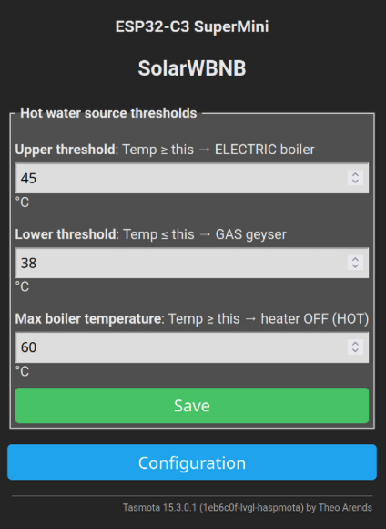
The custom configuration menu
The custom “Configure SolarWBNB” menu is a completely new menu, added in the autoexec.be. Here the user can configure both thresholds for the valve algorithm, and also the maximum watertemperature for the heating algorithm.
Berry crashes, how to stop it
If Berry autoexec.be crashes, the system becomes unbearable slow, and nothing works anymore.
You can try removing the whole script by pasting this in the browser:
http://10.0.3.129/ufsd?delete=/autoexec.be&download=/
This saved me a few times.
Domoticz integration - Heater Mode
Context
The autoexec.be code uses the variable hmode:
hmode # 0: AUTO, 1: MANUAL, 2: ERROR
Semantics: When on AUTO, the heater element will automatically warm the water
if excess energy is available.
When on MANUAL, it stops the heating completely, so no electricity is consumed.
This variable can be changed by the user from AUTO to MANUAL and vice versa in the Tasmota WebUI.
We wish to be able to see the value of this variable in Domoticz.
We wish to be able to toggle this variable from Domoticz.
Architecture of the solution
We will make a “dummy” device in Domoticz, and couple it to the Tasmota variable.
We have to be carefull, to prevent Tasmota from sending an update message to Domoticz when the request came from Domoticz, and vice versa, since that would cause a feedback loop of MQTT messages.
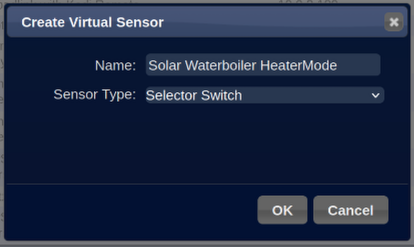
Create dummy device
Go to the Domoticz hardware list under the setup menu.

Fill in the name “Solar Waterboiler HeaterMode” and the type “Selector Switch”. A selector switch in Domoticz is a kind of switch that may have multiple named positions.
Now, we go to the Devices list under the Setup menu, and sort on the “Idx” column; here we find our new device:

The Idx is the unique identifier in Domoticz, we need to remember this number for later.
Set the possible values
Go to the “Switches” tab of Domoticz, scroll to the bottom, and look at the device:

We need to rename the values, by default they are Off, Level1, Level2, Level3. These need to become Auto, Manual, Error.
So, we press the “Edit” button:
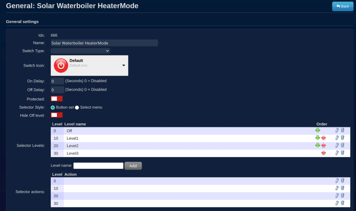
- Choose an icon
- Rename the 3 selector levels
- Remove the 4th selector level
- Set the Selector actions
The selector actions directly invoke the commands we created in the Berry code
via the Tasmota API with URL: http://SolarWBNB/cm?cmnd=HeaterModeAuto’.
We do not need a selector action for the error state, since we do not want the user to put the Tasmota module into error state.

Press Save. This looks already better:

Pressing these buttons “Auto” and “Manual” in Domoticz works now. So, updating Tasmota from Domoticz works now.
Updating Domoticz from Tasmota
In the autoexec.be,
we include statements like below,
when the hmode is changed by the user in the Tasmota WebUI.
We publish a MQTT message in the syntax from Domoticz for the
device with the index of the device and the new value.
self.hmode = self.HMODE_AUTO
...
# Warn Domoticz, 0 = Auto, the nvalue is not needed
mqtt.publish("domoticz/in", '{ "idx": 686, "svalue":"0"}')
and:
self.hmode = self.HMODE_MANUAL
...
# Warn Domoticz, 10 = Manual, the nvalue is not needed
mqtt.publish("domoticz/in", '{ "idx": 686, "svalue":"10"}')
We do NOT send such MQTT message in case the Tasmota command
(that we created) HeaterModePause or HeaterModeAuto is triggered,
since this is normally only done by Domoticz,
and that would only cause a feedback loop of messages going to and fro.
Conclusions
I recorded the temperature in Domoticz, see graph below. It started May 14th with water of 20°C. The first few days, the weather was not good, so the maximum temperature was not reached. Anyhow, we could still enjoy showering with water warmed by the sun!

Later in the month, it was very sunny:

Everything works very good, no problem.
I did everything myself, except for the help from my brother, mainly for the plumbing - thanks to him!
Since I bought a second-hand boiler, this DIY project costed me only around 300€.
I expect to win that money back in 2 or 3 years,
and in the meanwhile I use less natural gas.
This was a nice project, I am happy with it.